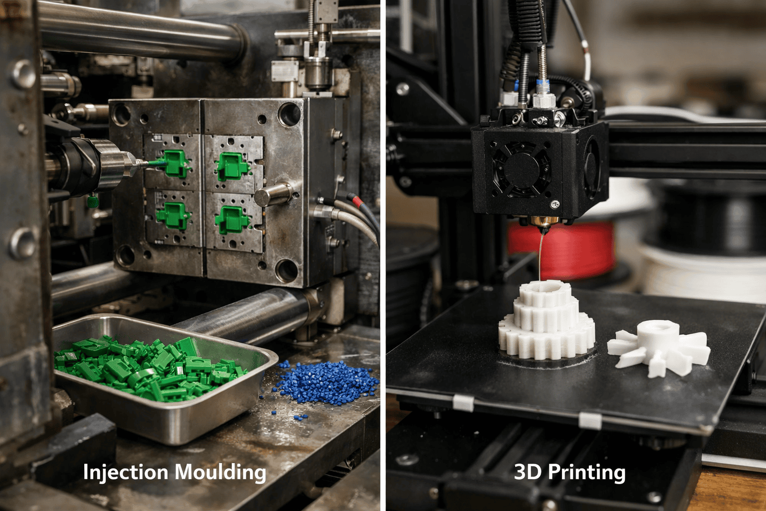
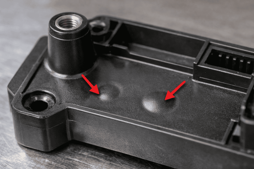
Sink marks are depressions or dimples on the surface of an injection-moulded part, caused when the outer skin cools and solidifies before the material underneath has fully contracted. They appear most often above thick sections, ribs, and bosses, where thermal mass slows internal cooling. This article examines the seven principal root causes from wall thickness imbalances to insufficient packing pressure and provides specific corrective actions for each.
Key takeaways
- Check wall thickness uniformity first, uneven thickness is the most common cause of sink marks.
- Verify part temperature at ejection using a contact pyrometer before shortening cooling cycles.
- Keep rib thickness at 50–60% of the adjoining nominal wall to prevent localised heat mass.
- Set packing pressure at 50–80% of injection pressure and extend pack time until gate freeze-off is confirmed.
- Dry hygroscopic resins correctly: nylon 6 needs 4–6 hours at 80°C; polycarbonate needs 4 hours at 120°C.
- Use desiccant dryers reaching −40°C dew point standard hopper dryers are rarely sufficient.
- Keep mould temperature differential below 10°C between cavity and core to prevent uneven shrinkage.
What Sink Marks Are and Why They Form
Check wall thickness uniformity before any other variable when diagnosing sink marks. Uneven thickness is the most common structural condition that allows them to form, and addressing it early eliminates several downstream causes at once.
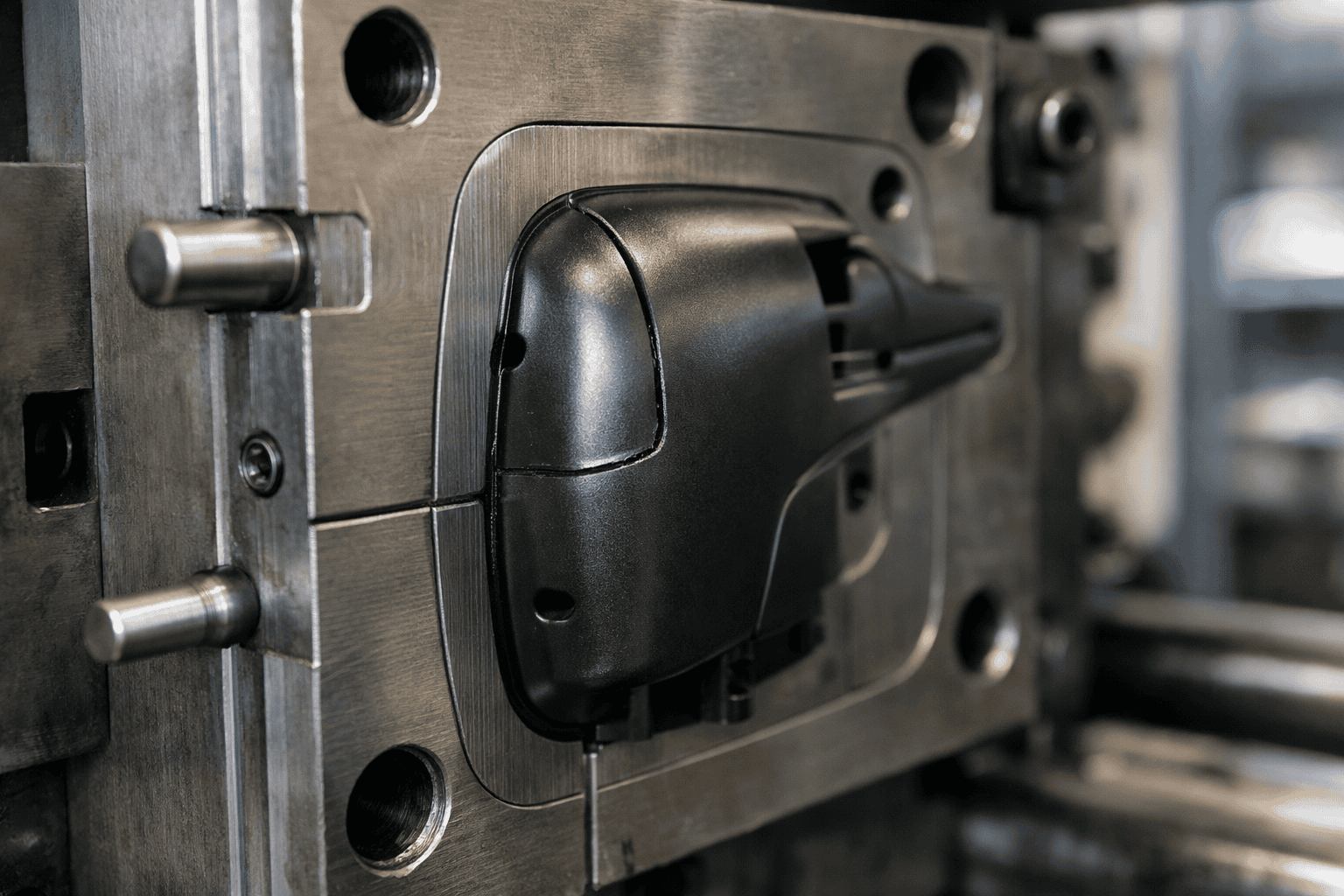
Sink marks appear on the outer surface of an injection-moulded part directly opposite a thick section, rib, or boss. As molten plastic cools, the outer skin solidifies first. The material beneath continues to shrink, pulling the skin inward before it has enough rigidity to resist. The result is a shallow depression sometimes barely visible, sometimes a pronounced concavity on what should be a flat or uniformly curved surface.
The physics behind this are straightforward: plastics have high volumetric shrinkage rates compared to metals, typically between 0.5% and 3% depending on the material. Where mass is concentrated, there is simply more volume to lose during cooling. Insufficient packing pressure, premature gate freeze, and inadequate cooling time each amplify this effect rather than cause it independently.
Inadequate Cooling Time and Uneven Mould Temperature
| Condition | Root Cause | Symptom | Correction |
|---|---|---|---|
| Insufficient cooling time | Part ejected before thick sections solidify | Outer skin collapses inward under shrinkage stress | Extend cooling time until core drops below heat deflection temperature |
| Uneven mould temperature | Cooling channels closer to one cavity face | Asymmetric shrinkage profile across part surface | Use conformal cooling channels or reposition baffles and bubblers |
| Mould running too cold | Gate freezes prematurely | Pack pressure unable to reach deep sections — same effect as insufficient cooling | Check ejection temperature and temperature distribution across mould face |
Releasing a part before thick internal sections have fully solidified causes the outer skin to collapse inward under shrinkage stress, producing a visible depression. Cooling time should be long enough for the gate area and thick sections to drop below the material’s heat deflection temperature before ejection. Verify part temperature at ejection using a contact pyrometer or infrared sensor rather than shortening cycle time without confirming core temperatures.
Uneven mould temperature creates an asymmetric shrinkage profile when cooling channels run closer to one cavity face than the other. Conformal cooling channels address this by following cavity contours and delivering consistent heat extraction across complex geometry. On existing tooling, repositioning baffles or bubblers in problem zones can correct hotspots without a full tool rebuild.
A mould running too cold freezes the gate prematurely, preventing pack pressure from reaching deep sections producing the same result as insufficient cooling time but from the opposite cause. Checking both ejection temperature and temperature distribution across the mould face distinguishes the two conditions before any process adjustment.
Excessive Wall Thickness and Poor Part Geometry
Walls thicker than roughly 4mm in most commodity thermoplastics create a core that stays molten long after the outer skin solidifies. Shrinkage stress then pulls that skin inward, forming a sink mark.
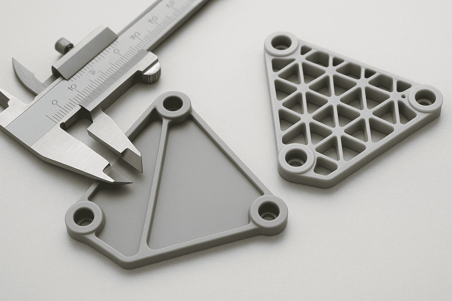
Rib thickness is where geometry problems concentrate. A rib exceeding 60% of the adjoining wall cools slower than its surroundings, creating a localised mass. The Society of Plastics Engineers recommends 50–60% of nominal wall thickness to avoid this. Bosses carry the same risk: a boss wall thicker than 60% of the nominal wall, or placed directly on a visible surface, almost always produces a sink directly opposite.
Uniform wall thickness lets the part shrink at a consistent rate. Where transitions are unavoidable, taper the cross-section at a ratio of at least 3:1 (length to thickness change) rather than stepping abruptly. For sections requiring more material, coring out from the non-visible face achieves the same stiffness at lower mass, removing the condition that causes sink.
Insufficient Packing Pressure and Gate Design Faults
Low packing pressure is the most direct process correction for sink marks. When the pack phase ends too early or at insufficient pressure, the cavity lacks volume to compensate for shrinkage and the surface draws inward. Set packing pressure between 50% and 80% of injection pressure, then extend pack time until gate freeze-off is confirmed weigh consecutive shots to find it.
Gate size and location govern how long the pack phase remains effective. A gate that freezes before the cavity is fully compensated cuts off material flow regardless of pressure. The Plastics Industry Association recommends sizing gates to at least 50–80% of wall thickness for amorphous resins, positioned adjacent to the thickest cross-section.
If the gate cannot be repositioned, increasing its diameter extends the freeze-off window. Check runner diameter too: an undersized runner creates pressure drop before material reaches the gate, making machine-side packing adjustments ineffective.
Material Selection and Moisture-Related Causes
- Volumetric shrinkage as low as 0.5%, reducing sink severity
- Less sensitivity to packing pressure variations
- Greater tolerance for minor wall thickness inconsistencies
- More predictable surface finish on visible faces
- Shrinkage rates up to 3%, amplifying sink mark formation at thick sections
- Require precise packing pressure and extended pack time to compensate
- Moisture absorption before moulding can introduce voids and surface defects
- Greater sensitivity to gate freeze timing and mould temperature uniformity
Hygroscopic resins nylon, ABS, polycarbonate, and PET absorb ambient moisture that converts to steam during moulding, creating voids and surface depressions often mistaken for packing faults. Nylon 6 requires 4–6 hours at 80°C; polycarbonate needs 4 hours at 120°C. Standard hopper dryers rarely achieve sufficient dew points desiccant or compressed-air dryers reaching −40°C are the reliable choice. Use a gravimetric moisture analyser before production runs if sink marks persist after other corrections.
Shrinkage rate varies by polymer class independently of moisture. Semi-crystalline materials such as acetal and nylon shrink 2–3% volumetrically roughly double the rate of amorphous grades like polystyrene or ABS which demands thinner walls, smaller ribs, and longer pack times. Switching to an amorphous grade reduces shrinkage-driven sink risk but requires revalidation of the part design and tooling.
High regrind content degrades molecular weight and reduces pack efficiency. Keeping regrind below 20% by weight preserves behaviour close to virgin material specification.
Process Adjustments and Tooling Fixes That Eliminate Sink Marks
Raise packing pressure first, then confirm gate freeze-off by weighing consecutive shots. Extend pack time in 0.5-second increments until shot weight stabilises, which confirms the gate has frozen before the pack phase ends. Keep mould temperature differential below 10°C between cavity and core; larger differentials cause uneven shrinkage that process adjustments alone cannot correct.
When process changes fail, the tool needs modification. Enlarging an undersized gate extends the packing window and is often the most effective single fix. Relocating the gate closer to a thick section reduces the flow length pack pressure must overcome. Where ribs exceed 60% of nominal wall thickness or bosses lack sufficient coring, removing steel from the cavity corrects the thermal imbalance at source.
Material changes should follow process and tooling corrections. Glass-filled grades with lower shrinkage rates reduce the volume differential that causes surface collapse, but switching resin without addressing the underlying geometry or packing fault reduces mark severity rather than eliminating it. Confirm the root cause first, then select the fix in order of cost and lead-time: process adjustment, tooling modification, material change.
Frequently Asked Questions
What causes sink marks in injection moulded parts?
Sink marks form when the outer skin of a moulded part cools and solidifies before the interior, leaving insufficient material to compensate for internal shrinkage. The result is a localised depression on the surface. Common causes include excessive wall thickness, inadequate packing pressure, poor gate placement, and insufficient cooling time.
How do thick sections and inconsistent wall thickness lead to sink marks?
Plastic cools and shrinks as it solidifies. In thick sections, the outer skin hardens first while the core remains molten for longer, pulling the surface inward as it contracts. Abrupt transitions between thick and thin walls intensify this effect by creating uneven cooling rates across the part.
How do packing pressure and packing time affect sink marks, and how can they be adjusted?
Raise packing pressure until the sink disappears, then lock in the shortest packing time that holds that result. Insufficient pressure leaves voids beneath the surface as the material shrinks. Packing time controls how long the gate stays open to compensate for that shrinkage cut it too short and material pulls back before the part solidifies.
Which material properties and processing temperatures increase the risk of sink marks?
High shrinkage rates are the primary risk factor. Semi-crystalline polymers such as nylon, acetal, and polypropylene shrink significantly more than amorphous materials like ABS or polycarbonate, making them inherently prone to sink marks. Elevated melt temperatures and insufficient mould cooling compound this by extending the time thick sections remain molten beneath a solidified skin.
What mould and gate design changes help eliminate sink marks without causing warpage or flash?
Gate placement within 25–30% of the wall thickness nearest the heaviest section gives melt the shortest path to the sink-prone area. Positioning gates at the thickest point lets packing pressure reach the core before the material freezes. Keep vents at flow endpoints to prevent trapped gas, which causes both sink marks and localised burning without requiring gate repositioning.