Gate design controls how molten polymer enters the cavity, shaping fill pattern, weld lines, and surface finish. In injection moulding, the gate also sets pressure loss and shear rate, which can change part strength and appearance. A 0.5 mm change in gate thickness can shift fill time by several tenths of a second on short-cycle tools, while poor placement can raise scrap rates by 5–15% in high-volume runs.
This guide reviews common gate types and explains when each suits thin walls, cosmetic surfaces, multi-cavity tools, or automated de-gating. It also outlines practical selection criteria, including material viscosity, runner layout, and target cycle time.
Key takeaways
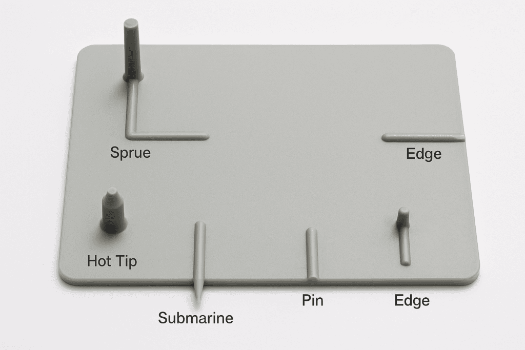
- Gate choice controls fill pattern, weld lines, sink risk, and cosmetic finish.
- Edge and fan gates suit flat parts, spreading flow to reduce shear.
- Pin and submarine gates enable automatic de-gating on small to medium components.
- Hot tip and valve gates support hot runners, cutting waste and improving consistency.
- Diaphragm and ring gates fill cylindrical parts evenly, reducing warpage and knit lines.
- Direct sprue gates suit thick, simple parts but leave larger vestige marks.
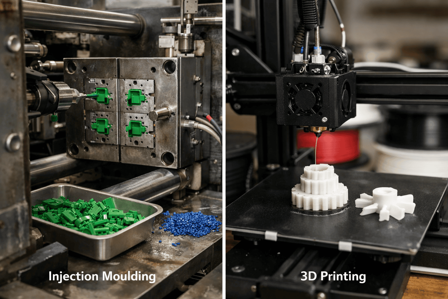
What an injection moulding gate does: flow control, packing pressure, and vestige
In a typical injection moulding cycle, the gate controls melt flow for roughly 1–5 seconds, then “freezes” to end packing and start cooling. That short window drives a large share of part quality because the gate sets the flow rate into the cavity, the pressure available for packing, and the size and location of the vestige left after separation. A small change in gate geometry can shift peak cavity pressure by tens of bar, which often decides whether a part meets dimensional tolerance or shows sink and warp.
The gate acts as a calibrated restriction between runner and cavity. By throttling flow, the gate increases shear rate and shear heating at entry, which can improve fill in thin walls but also raises the risk of burn marks or material degradation if shear becomes excessive. In practical terms, a 10–20% reduction in gate thickness can noticeably increase injection pressure demand, while a wider gate can reduce pressure but may worsen cosmetic marks. This trade-off sits at the centre of what is plastic injection moulding for production parts: the gate must balance fill capability with surface finish and cycle time.
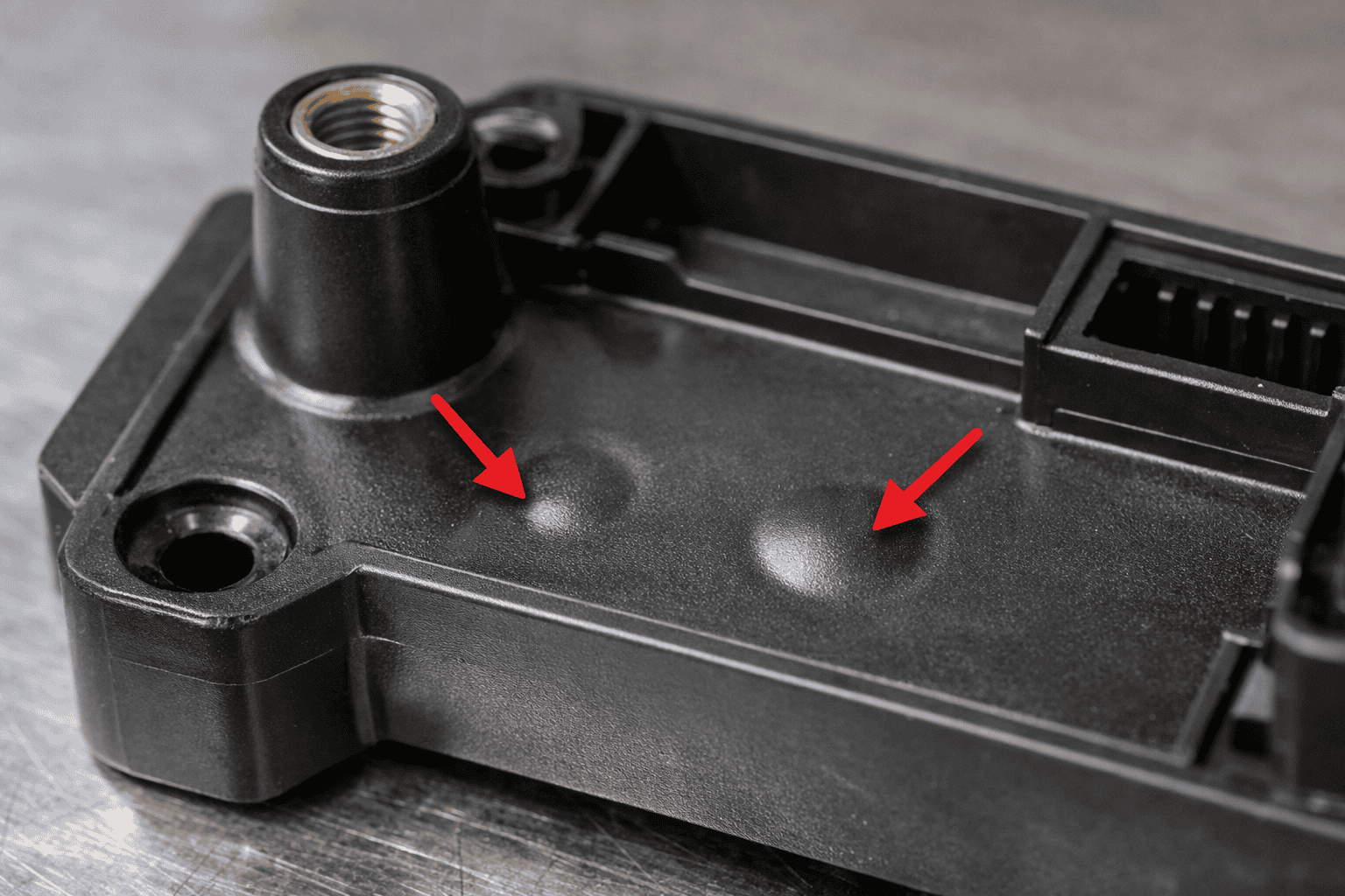
Packing pressure depends on how long the gate remains open before freeze-off. If the gate freezes too early, the machine cannot compensate for volumetric shrinkage, which typically ranges from about 0.4–0.8% for many amorphous polymers and about 1.0–2.5% for many semi-crystalline polymers (material- and grade-dependent). That shrinkage translates into sinks near thick sections and higher variation in weight, often visible as a 1–3% swing in part mass when packing becomes inconsistent. Designers often tune gate size and land length to keep the gate open long enough to pack, without extending cooling time unnecessarily.
The vestige is the physical evidence of the gate choice. A direct gate can leave a larger mark but supports high packing efficiency; a tunnel or valve gate can reduce vestige but may limit packing or increase tooling complexity. Many consumer-facing parts target a vestige under about 0.1–0.3 mm in height, while structural parts may accept more if it improves strength and dimensional stability.
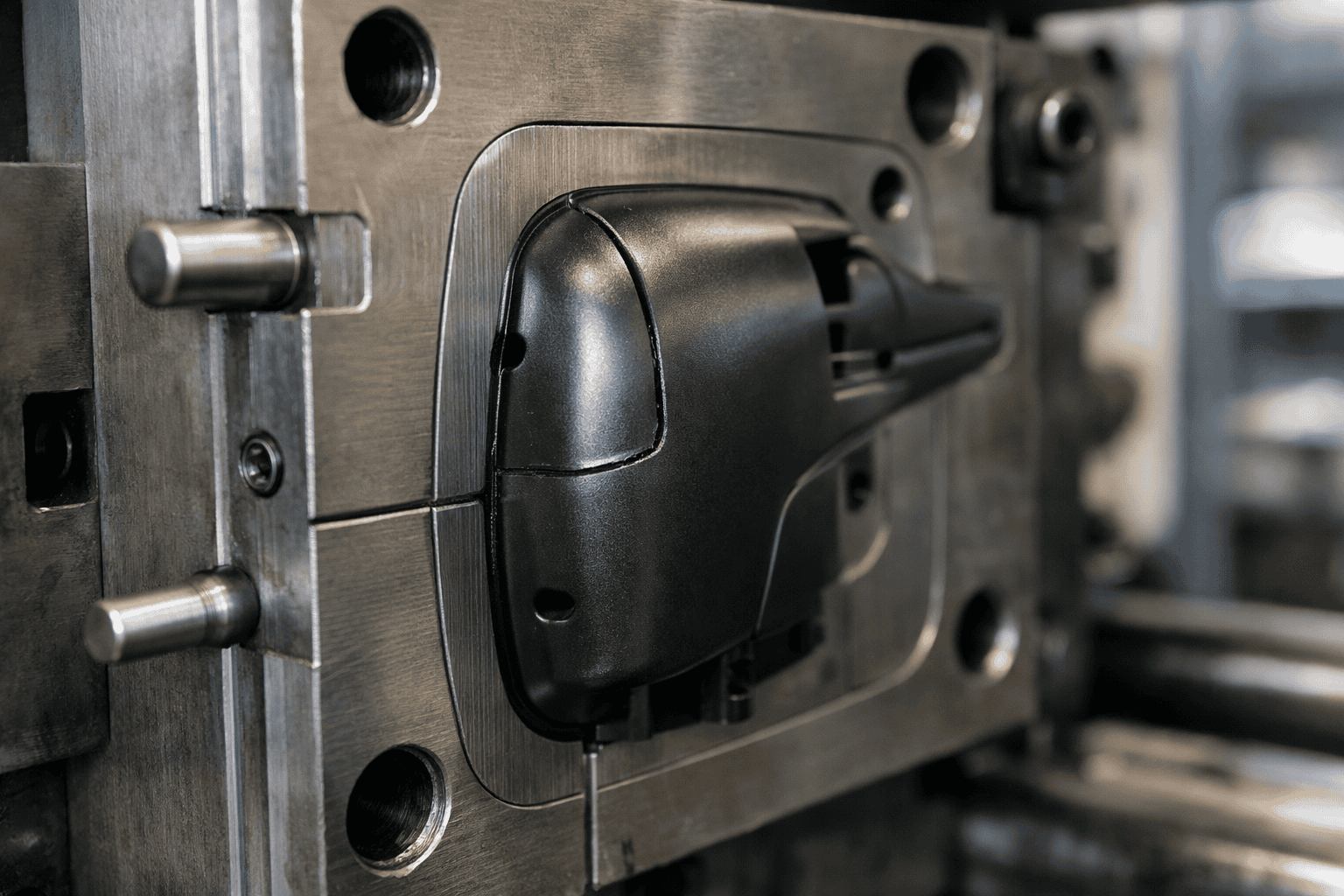
Edge and fan gates: when to prioritise simple tooling and low-cost production
A contract manufacturer producing a 220 mm-long ABS electronics enclosure needed 50,000 units in eight weeks, with a tooling budget capped at £12,000. The part had a 2.2 mm nominal wall, a cosmetic A-surface on the front, and a hidden flange along one long edge. The team chose an edge gate into the flange because it allowed a simple two-plate mould, standard sprue and runner layout, and a gate vestige that stayed off the visible face. With a 1.0 mm gate thickness and 8 mm gate width, the moulder achieved a 1.8–2.3 s fill time and held packing pressure until the gate froze at roughly 2.5–3.0 s, keeping sink marks away from the front panel.
That decision worked because edge gates favour straightforward machining and predictable processing. An edge gate feeds from the parting line, so the toolmaker can cut the gate with conventional milling and hand polishing rather than complex inserts. For medium-sized parts, the gate also supports robust packing because the gate cross-section stays relatively large, which reduces shear heating and helps maintain melt temperature into the cavity. When the gate sits on a flange, the vestige becomes a functional non-issue, and operators can trim it quickly without secondary finishing.
A fan gate applies the same low-complexity principle when the part needs a wider, gentler entry. By spreading flow across a broad gate land, a fan gate reduces jetting risk and lowers orientation-driven warp on thin, wide panels. In practice, moulders often size fan gates at 10–30 mm wide with a 0.6–1.2 mm thickness for 1.5–3.0 mm walls, then tune the taper to balance fill and gate freeze. This approach suits housings, covers, and nameplate-style parts where a uniform flow front matters more than a minimal vestige.
Use edge and fan gates when you prioritise low tool cost, short lead times, and reliable trimming, and when you can place the gate on a non-cosmetic edge. For dimensional stability, confirm the gate location and width against the resin supplier’s processing guidance, such as Covestro or DuPont, then validate with a short DOE on fill time and packing pressure to lock in the window.
Pin, submarine (tunnel), and cashew gates: automatic de-gating for high-volume parts
Pin, submarine (tunnel), and cashew gates all aim for automatic de-gating with minimal operator time. The trade-off sits between vestige control, tooling complexity, and how reliably the gate breaks across millions of cycles.
A pin gate feeds the cavity through a small circular land, typically 0.8–1.5 mm in diameter for many commodity parts, which keeps the vestige compact and predictable. A submarine (tunnel) gate enters below the parting line through an angled tunnel, so the runner pulls the gate and separates during ejection, often leaving a 0.2–0.6 mm witness on the underside. A cashew gate uses a curved tunnel that “hooks” the gate, improving break-off on tougher materials and reducing long strings, but it needs tighter machining control than a straight tunnel.
| Gate type | Automatic de-gating method | Typical vestige location | Best fit |
|---|---|---|---|
| Pin | Break at small land during ejection or part removal | On the part surface at the gate point | Cosmetic control, hot runner drops, multi-cavity tools |
| Submarine (tunnel) | Runner pulls gate through angled tunnel | Hidden underside or non-cosmetic edge | High-volume cold runner tools, reduced handling |
| Cashew | Curved tunnel promotes controlled snap-off | Hidden underside with smaller witness than straight tunnel | Ductile resins, stringing risk, tighter cosmetic limits |
Key differences appear in shear and break-off behaviour. Pin gates concentrate shear at the land, which can raise melt temperature locally and mark sensitive polymers; the small land also freezes quickly, which helps cycle time but can limit packing on thick sections. Submarine gates reduce visible vestige, yet the tunnel angle and gate thickness must match resin toughness; too thick and the gate hangs on, too thin and the gate can blush or crack the edge.
Choose pin gates when a hot runner justifies higher tooling cost and when a 16–64 cavity layout needs consistent fill balance. Use submarine gates when labour must approach zero and the witness can sit on a hidden face, common in 2–4 mm wall consumer housings. Select cashew gates when straight tunnels string on polypropylene or toughened ABS, and when controlled snap-off protects automated handling at 10,000+ parts per day.
Hot runner valve and thermal gates: balancing cycle time, material waste, and cosmetic requirements
Scrap and rework often spike when a cold runner accounts for 20–60% of shot weight on small parts, while a visible gate mark fails a Class A surface requirement. At the same time, a long runner can add 3–10 seconds of cooling time because the sprue and runner must solidify before ejection. Hot runner valve gates and thermal (hot tip) gates address these losses, but each option shifts the balance between cycle time, material waste, and cosmetic risk.
A valve gate uses a mechanically actuated pin to shut off melt flow at the gate, which reduces stringing and improves gate vestige control on exposed surfaces. A thermal gate relies on a heated tip and a frozen “skin” to seal the gate, which lowers system cost and simplifies maintenance, but can leave a larger blush or drool if the freeze-off window varies. For tight cosmetic specifications, valve gating often holds a smaller, cleaner vestige because the pin closes at a defined position rather than depending on polymer freeze behaviour.
Start implementation by quantifying the business case: measure runner-to-part ratio, regrind limits, and cycle time contribution from runner cooling. Next, size the gate to match the required fill time and shear limits; for many housings and caps, gate diameters commonly fall in the 0.8–1.6 mm range, but the correct value depends on polymer viscosity and wall thickness. Then set a process window using cavity pressure or transfer position, and validate shut-off timing; a 0.05–0.20 second change in valve close timing can shift gate blush and sink risk on thin walls.
Results should show up in three metrics: reduced material waste, shorter cycles, and fewer cosmetic rejects. A hot runner typically eliminates runner scrap entirely, while stabilising part weight because the melt path stays at temperature. Confirm performance with a short DOE on melt temperature, hold pressure, and gate close/freeze time, and document acceptance limits for vestige height and gloss variation using a repeatable inspection method such as ISO 2813 gloss measurement.
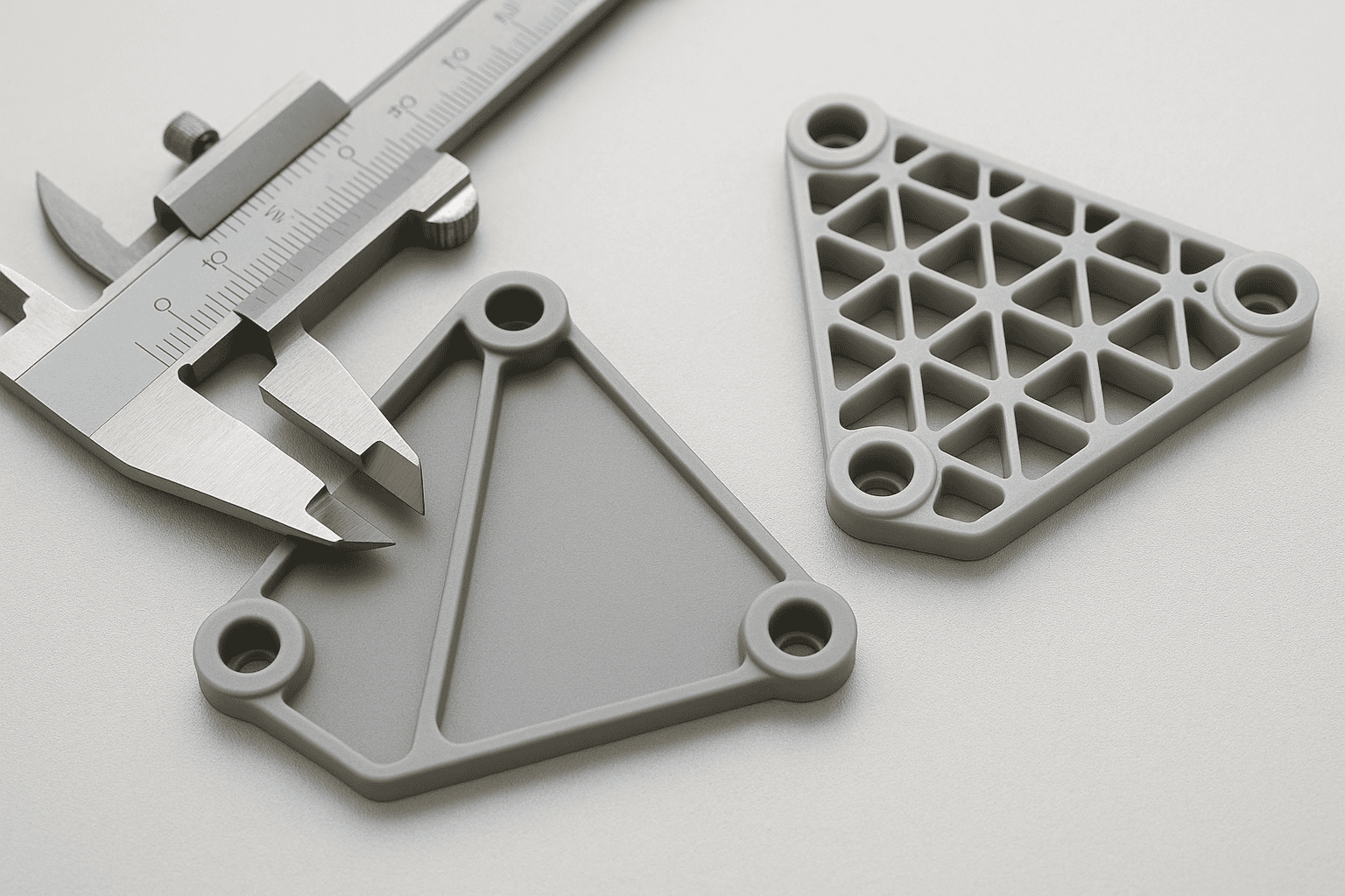
How to choose the right gate: resin behaviour, part geometry, weld lines, and quality checks
In 2024, PLASTICS reported that the United States produced about 7.2 million tonnes of plastic products, a scale that makes small gate decisions measurable in scrap, rework, and inspection time. Gate selection changes how the melt shears, how fast the gate freezes (often within 1–5 seconds), and how much packing pressure reaches the last-to-fill regions. Those variables control sink, gloss variation, and dimensional drift, especially on thin walls below 2.0 mm.
Start with resin behaviour because viscosity and shear sensitivity dictate the safe gate velocity. Semi-crystalline materials such as polypropylene shrink more during cooling than amorphous resins, so the gate must stay open long enough to pack without over-shearing the melt. A practical check uses cavity pressure: if peak pressure rises above the process window while the part still shows sinks, the gate likely restricts packing or freezes too early. That pattern often appears when the gate land runs long or the gate thickness drops below about 50–70% of nominal wall.
Part geometry then narrows the options. Long flow lengths, ribs, and abrupt thickness changes increase pressure drop and raise the risk of hesitation marks. Place the gate to fill thick-to-thin where possible, and avoid directing the first melt front across a cosmetic face that must meet a defined gloss. When the design forces multiple flow fronts, treat weld lines as a functional feature: move the gate so the weld line lands on a non-critical edge, or increase melt temperature and injection speed to improve knit strength without flashing.
Quality checks should close the loop. Use short shots to confirm fill pattern, then validate gate freeze time by stepping hold time until part weight stabilises within 0.2–0.5%. Dimensional capability should follow with a Cp/Cpk study on key features, because a gate that looks acceptable can still drive warpage through uneven packing. If tooling changes or hot runner upgrades affect budget, align the decision with how much does injection moulding cost so gate choice reflects both quality risk and unit economics.
Frequently Asked Questions
What factors determine the best gate type for a specific injection moulded part?
The best gate type depends on part geometry and wall thickness, resin viscosity and shear sensitivity, cosmetic requirements, and required fill balance. It also depends on gate vestige limits, weld line and air trap risk, and the need for automatic degating. Tooling constraints matter, including available parting lines, hot runner use, and cycle time targets.
When should a manufacturer choose an edge gate instead of a fan gate in injection moulding?
Choose an edge gate when the part tolerates a small, localised gate mark and needs a simple, low-cost tool. Edge gates suit short-to-medium flow lengths (often <150 mm), moderate wall thickness (about 1.5–4.0 mm), and higher injection pressures. Use a fan gate when you must reduce shear, improve fill uniformity, or limit warpage on wide, thin sections.
How do pin gates and submarine (tunnel) gates differ in vestige size and automation suitability?
Pin gates leave a small, circular vestige, typically about 0.3–1.0 mm in diameter, but often need manual or secondary degating. Submarine (tunnel) gates shear off during ejection, leaving a slightly larger witness mark, often about 0.5–1.5 mm, and suit high-volume, fully automated moulding with minimal post-processing.
What are the main advantages and limitations of hot tip and valve gate systems for high-volume moulding?
Hot tip gates suit high-volume moulding because they cut cycle time and scrap by eliminating runners, and they reduce post-processing. Limitations include higher tooling cost, tighter temperature control, and risk of stringing or gate blush on some resins. Valve gates add precise shut-off, cleaner vestige, and better fill balance, but increase complexity, maintenance, and capital cost.
How does gate location influence weld lines, sink marks, and warpage in injection moulded components?
Gate location controls flow fronts, packing pressure, and cooling balance. Placing the gate where flow meets in low-stress, hidden areas reduces weld lines; poor placement can force weld lines across ribs or holes. Gating near thick sections improves packing and cuts sink marks. Centred, symmetric gating shortens flow length and reduces differential shrinkage, limiting warpage.