A parting line in injection moulding is the seam where the mould halves meet and separate, leaving a visible line on the moulded part. Its position depends on the tool split, draft angles, shut-offs, and how the part ejects without damage.
This guide explains common parting line locations, how they affect appearance and function, and how to specify acceptable seams on drawings. It also covers design tactics to hide or control the line, reduce flash risk, and avoid weak edges in critical areas.
Key takeaways
- Place the parting line on non-cosmetic faces to hide witness lines and mismatch.
- Keep shut-off surfaces wide and robust to reduce flash and tool wear.
- Avoid parting lines across critical sealing faces; move them to a controlled land.
- Use consistent draft on both sides of the split to prevent scuffing during ejection.
- Break up complex geometry with stepped parting lines only where machining access stays simple.
- Design ribs, bosses, and holes to avoid split features that create mismatch and burrs.
How parting lines form in injection moulding and what they indicate about the tool
Mark the preferred parting line on the CAD model before you request a quote, then confirm it with the toolmaker. That single decision fixes where the mould halves meet, which controls flash risk, witness marks, and how the tool vents air.
A parting line forms where the cavity and core separate, and it often follows the highest points of the geometry along the draw direction. If the surface steps across the split, the tool needs shut-offs (metal-to-metal sealing faces) to stop melt escaping. Thin shut-offs wear faster, so a busy parting line can indicate higher maintenance and tighter process control.
Expect the line to sit on non-cosmetic faces, away from sealing surfaces, snap fits, and datum features. When the line must cross a visible area, specify texture and gloss targets early so the toolmaker can blend the split and plan polishing. For broader context on Injection Moulding and downstream finishing in Plastic Manufacturing, align parting line placement with the full production route, not just the tool design.
Common parting line locations: shut-offs, slides, lifters, and multi-part mould interfaces
| Mould Type | Key Parting Line Features | Lifetime Maintenance Cost | Typical Cycle Rating |
|---|---|---|---|
| Simple flat parting line, no side actions | Single-plane shut-off only | 5–10% of original tooling cost | Class 104: up to 100,000 cycles |
| Medium complexity with slides or lifters | Shut-offs + slide parting interfaces | 15–25% of original tooling cost | Class 103: up to 500,000 cycles |
| High-volume, multi-action mould | Shut-offs, slides, lifters, multi-part interfaces | 30–40% of original tooling cost | Class 101: 1,000,000+ cycles |
Source: Plastics Today — Tooling Corner: What is a Mold Worth? (2023); Crescent Industries — Top 10 Factors that Shape Injection Mold Tooling Costs
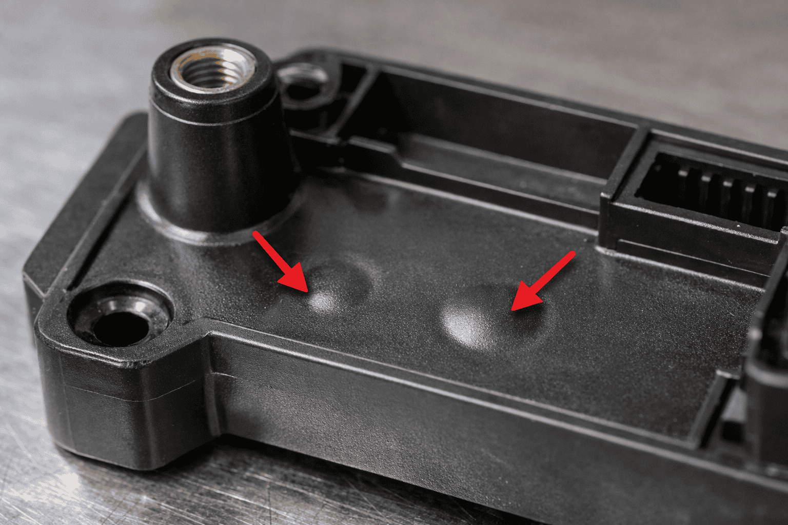
A visible witness mark can force secondary finishing, tighten cosmetic tolerances, and raise scrap if flash appears at shut-offs. Place the parting line on non-cosmetic faces and keep it on a single plane where possible, then design shut-offs with generous land length and draft so the tool seals reliably.
This approach works because shut-offs, slides, and lifters add moving interfaces that wear and deflect under clamp force. Each interface can leak melt, especially where thin steel meets high injection pressure. Clean, well-drafted shut-offs also vent predictably, which helps stabilise fill and supports lower rates in injection moulding.
Use slides when side actions protect critical features such as undercuts or side holes, but keep the slide parting line off show surfaces and avoid feather edges. Use lifters for small internal undercuts, accepting that the lifter split can print through on nearby faces. Multi-part mould interfaces (insert splits, cavity blocks, and interchangeable cores) suit serviceability or variant geometry, provided you control alignment with robust leadering and support pillars.
Functional risks tied to parting lines: flash, mismatch, witness marks, and sealing failures
Source: Evok Polymers — Flash Defects in Injection Molding (2025); Tederic Solutions — Injection Molding Defects (2025)
Assuming the mould will “seal itself” under clamp force is a common mistake; tool deflection, wear, or contamination can open a gap at the split and create defects.
Molten polymer hits the parting line at high pressure, so any loss of contact causes flash. Poor cavity-core registration creates mismatch, can shear fibres in filled materials, and weakens edges. Even with a seal, meeting faces can leave witness marks where melt cools against colder steel, especially with poor venting and air burns.
These issues show up as sealing failures on O-ring lands, leaky housings, and poor fit between mating parts. Treat the parting line as a controlled interface: keep sealing faces away, add land length on shut-offs, and set measurable limits for flash and mismatch in drawings and quotes. Cost pressure can loosen tolerances, so tie requirements to early commercial talks, including how much does injection moulding cost once scrap and rework are included.
Design rules to control parting lines: draft, radii, texture breaks, and cosmetic zoning
The parting line forms where geometry forces the tool to split, so geometry choices control the mark.
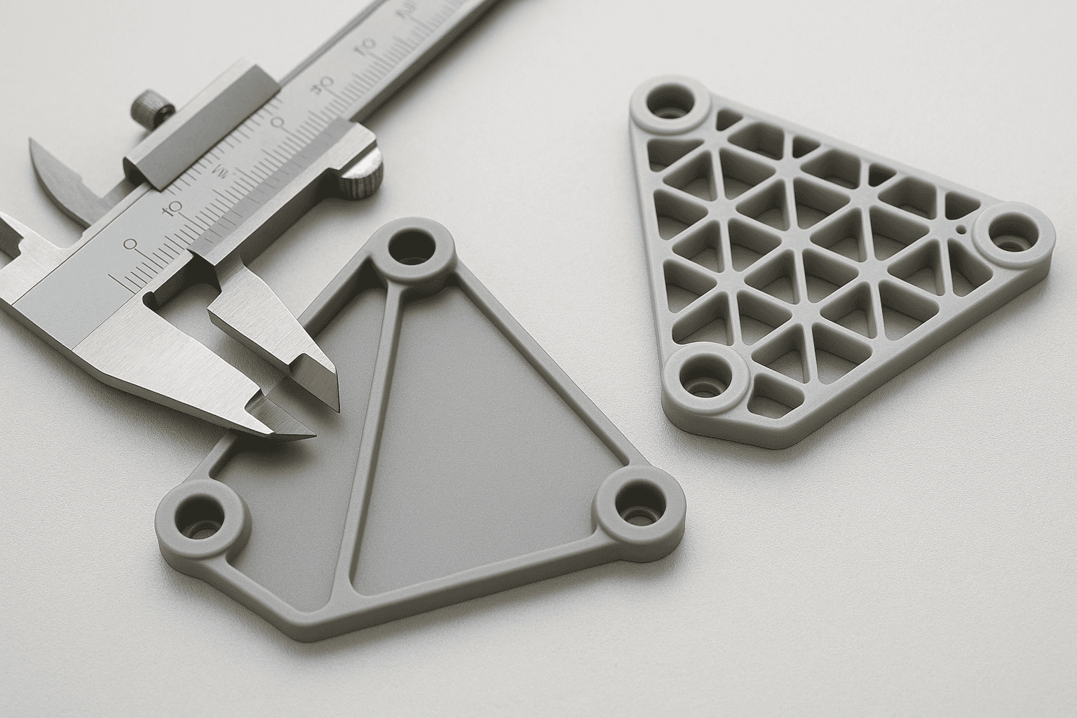
Add draft to faces at the split and align it with the draw. Increase draft on textured surfaces so texture does not break at the parting line. Add radii to edges that cross the split; even small radii cut local pressure, help mould faces seat, and reduce mismatch and flash. If you need a crisp edge, use a planned texture break or shallow step to hide the line, not an open cosmetic face.
Set cosmetic zones early: nominate A-surface areas that must stay free of parting lines, then push the split to B- or C-surfaces, underside faces, or shadow lines. Confirm zoning and draft with your toolmaker using section views and a draw-direction check in CAD.
Avoid zero-draft shut-offs, sharp corners at the split, and textures that run across the parting line; each makes the witness harder to control and polish.
Tooling and process levers to minimise visibility and defects: steel conditions, venting, and clamp force
Flash — which originates at parting lines, shut-offs, and slide interfaces — is the single most reported defect category. Together, these 6 defect types account for 91% of all injection moulding quality failures. Relative frequencies are illustrative based on published industry ranking data.
Source: Tederic Solutions — Injection Molding Defects Identification & Solutions (2025)
When tooling and process settings are dialled in, parting lines stay tight, flash drops, and witness marks are easier to control. Start with steel conditions: clean, flat, well-supported parting faces seal at lower clamp force, while worn shut-offs and bruised edges print defects even on stable machines. Toolmakers may add local “kiss-off” lands or adjust shut-off angles to keep contact where pressure peaks.
Venting controls how hard the melt pushes on the split. Trapped air stalls the melt front, raises pressure, and can part the tool slightly, showing as flash or burn. Use shallow vents at the parting line and keep them clear; blocked vents behave like no vents. Gate location and fill speed shift pressure at the split, so confirm settings during trials, not nominal clamp tonnage.
Clamp force should match projected area and cavity pressure, not “as high as possible”. Excess tonnage can deflect platens, accelerate wear, and still fail to seal a damaged interface. Draft supports sealing and ejection, so align it with the split and review why draft angles matter in mould design before freezing the tool.
Frequently Asked Questions
What is a parting line in injection moulding, and how does it form during mould opening and closing?
A parting line is the visible seam where the two mould halves meet on a moulded part. It forms at the split plane when the mould closes and the cavity and core align, leaving a fine interface. When the mould opens, the halves separate along that plane, and any slight mismatch or flash makes the line more noticeable.
How do mould designers choose the parting line location to balance appearance, ejection, and tooling constraints?
The parting line rarely sits where it looks best; it must also let the tool open cleanly and release the part. Designers place it on a natural edge or non-cosmetic face, then set draft so all features pull in one direction. Ejector pins, slides, lifters, gates, and venting must fit without creating undercuts or weak shut-offs.
Which part geometries and features make parting lines harder to control, and how can the design reduce risk?
Design the part so the mould can split on a single, continuous plane and keep key surfaces away from that split. Complex shut-offs, deep undercuts, and sharp texture breaks force stepped parting lines and increase flash risk. Reduce risk with generous draft, consistent wall thickness, radiused transitions, and by moving ribs, bosses, and cosmetic faces off the split.
How do parting lines affect flash, shut-off integrity, and dimensional accuracy on moulded parts?
If the parting line sits on a high-pressure flow path or a weak shut-off, defects rise fast. Poor shut-off integrity lets melt escape as flash, especially where faces are narrow, worn, or misaligned. Parting-line mismatch and clamp deflection also shift the split, hurting dimensional accuracy and creating steps that change critical fits.
What design changes help hide or minimise visible parting lines on cosmetic surfaces without increasing tooling complexity?
A 0.2–0.5 mm step or recess can move the parting line off the main cosmetic face. Place the split on a natural break such as a rib edge, corner radius, or texture boundary, and add a small chamfer to soften the witness. Use light texture or a matte finish to mask any remaining line.