Reducing part weight can cut material costs, improve efficiency, and support better performance. The challenge lies in removing mass without weakening the component or shortening its service life. This guide explains practical ways to lower weight while keeping strength, using clear design choices, suitable materials, and sound manufacturing methods. It also highlights common trade-offs, such as stiffness, fatigue resistance, and safety margins, so each change supports reliable, repeatable results.
Key takeaways
- Use topology optimisation to remove low-stress material while preserving load paths.
- Switch to high-strength alloys or fibre composites to cut mass at equal strength.
- Add ribs, beads, and gussets to raise stiffness without thickening entire walls.
- Replace solid sections with hollow profiles, lattices, or cores where buckling risk stays low.
- Reduce weight through part consolidation, removing fasteners and overlapping material in joints.
- Validate changes with FEA and physical tests, checking fatigue, impact, and safety factors.
Material selection strategies for high strength-to-weight performance
Material choice often sets the limit for weight reduction. A practical aim involves maximising strength-to-weight ratio, which compares how much load a material carries against its mass. Engineers can achieve a lighter part without sacrificing performance by selecting materials that match the dominant load case, the service temperature, and the environment.
Aluminium alloys suit many stiffness-led designs where bending drives failure, as aluminium offers low density with good corrosion resistance. When fatigue governs life, specific grades and heat treatments can raise endurance, although designers must still control stress concentrations. Titanium alloys provide higher strength at moderate weight and retain properties at elevated temperatures, which makes titanium attractive for aerospace and high-performance applications. Cost and machinability often limit use, so titanium tends to suit critical parts rather than commodity components.
Fibre-reinforced polymers can deliver exceptional directional strength when fibres align with principal loads. Carbon fibre composites can reduce mass sharply, yet impact damage and through-thickness weakness require careful lay-up design and inspection planning. For guidance on composite design allowables and test methods, consult ASTM International.
High-strength steels remain relevant when space constraints demand high stiffness and toughness in a compact section. Advanced high-strength grades can cut gauge while maintaining crash or overload performance, although corrosion protection and weld procedure control become more critical as thickness falls.
Material selection also benefits from data-driven screening. Use verified property databases and require traceable mill certificates, since small property gaps can erase predicted weight savings. Where uncertainty remains, confirm assumptions with coupon testing that reflects real manufacturing routes, surface finishes, and joining methods.
Geometry optimisation: load paths, ribbing, and wall thickness control
Geometry often delivers the largest weight savings once a suitable material is set. Start by mapping load paths, which describe how forces travel from the point of application to the supports. A part performs best when its shape guides those forces through continuous, direct routes. Sharp corners, abrupt section changes, and isolated bosses interrupt load flow and create stress concentrations, which raise the risk of cracking. Use generous fillets, smooth tapers, and aligned features so the part carries load through membrane and bending action with fewer local peaks.
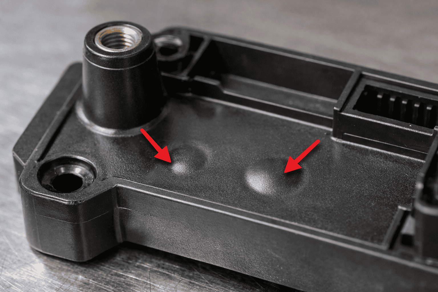
Ribbing provides stiffness without the mass of a fully thickened wall. Place ribs along principal stress directions and connect ribs into closed loops where possible, since closed sections resist torsion efficiently. Keep rib roots well radiused and avoid very tall, thin ribs that can buckle under compression. When a rib meets a wall, blend the junction to reduce notch effects. In moulded parts, maintain draft and avoid abrupt rib-to-wall thickness jumps to limit sink marks and residual stress.
Wall thickness control matters as much as rib layout. Thin walls reduce mass, yet excessive thinning can increase deflection and move stress into fasteners or joints. Aim for uniform thickness across large areas, then add material only where loads enter, where constraints exist, or where contact occurs. Use local thickening as pads or bosses with smooth transitions rather than broad, heavy sections. For bending-dominated parts, prioritise section depth over bulk, since stiffness scales strongly with the second moment of area.
Simulation helps validate these choices. Use finite element analysis to confirm that stress follows the intended load paths and that ribs and thickness changes reduce peak stress rather than shift it. For guidance on modelling practices and verification, refer to NASA technical resources on structural analysis and validation.
Manufacturing and process choices that enable lighter parts without defects
Process selection often decides whether a lightweight design reaches production without scrap, distortion, or hidden weakness. A sound approach starts with the dominant failure risks for the chosen process, such as porosity in castings, voids in mouldings, or lack of fusion in welds. When a process controls those risks well, engineers can specify thinner walls, smaller bosses, and tighter tolerances with confidence.
For metal parts, forging and cold forming can raise strength through grain flow alignment and work hardening, which may allow a smaller section for the same load. Machining from billet offers high quality but can waste material and introduce residual stress if heavy stock removal heats the part. Stress-relief heat treatment and stable fixturing reduce distortion, which helps maintain thin features. Where welding joins thin sections, joint design matters as much as the weld itself. A continuous load path through the joint, controlled heat input, and post-weld inspection reduce the chance of fatigue cracks starting at the toe.
For cast components, gating and riser design influence shrinkage and porosity, which can undermine strength even when the geometry looks correct. Foundries often use simulation to predict fill and solidification; Autodesk Moldflow provides a well-known example for mould filling analysis. Vacuum-assisted casting, degassing, and clean melt practice also support thinner walls by lowering defect rates.
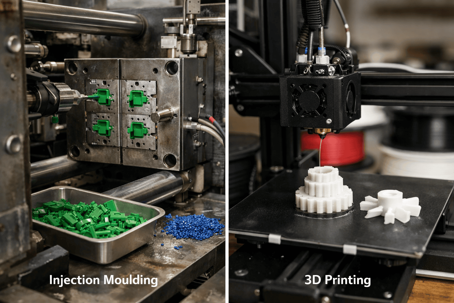
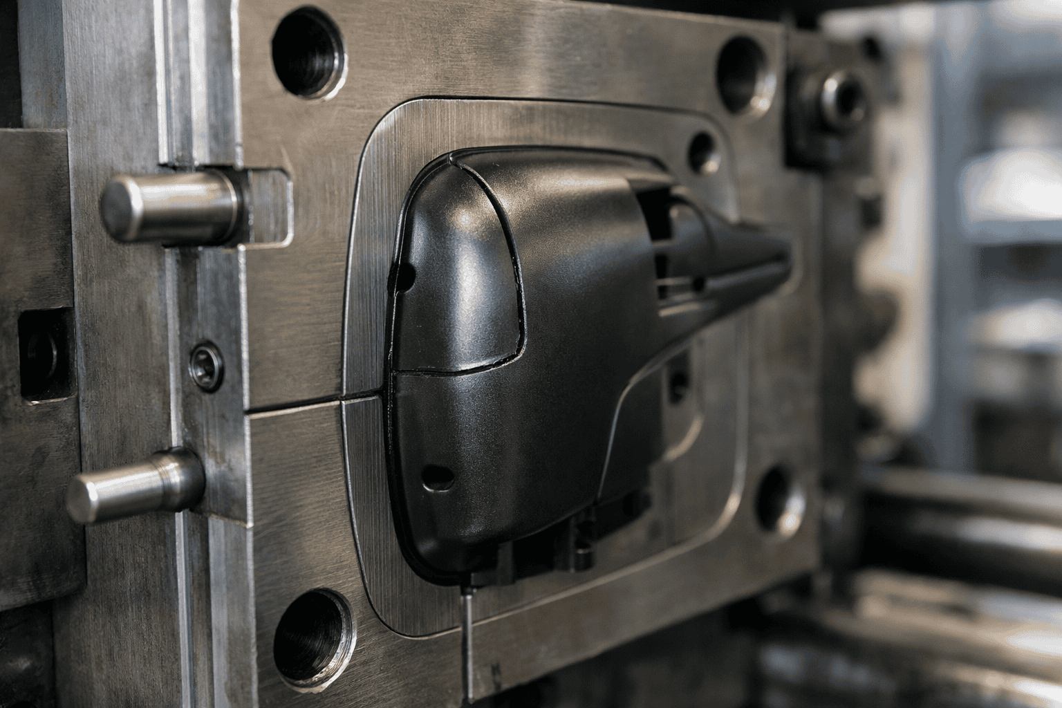
For polymer parts, injection moulding can produce very light structures, yet thin walls raise the risk of short shots, warpage, and weld lines. Balanced flow, correct gate placement, and controlled cooling reduce those issues. Fibre-reinforced polymers can deliver high stiffness at low mass, although fibre orientation follows flow, so tool design must align fibres with the main load direction. Process capability studies and non-destructive testing, such as X-ray computed tomography for critical parts, help confirm that weight reduction has not introduced internal defects.
Validation and testing methods to confirm strength after weight reduction
Weight reduction changes stiffness, stress distribution, and failure modes, so validation must confirm that the revised design still meets the original requirements. Start with a clear test plan that ties each requirement to a measurable acceptance criterion, such as maximum deflection under a defined load, fatigue life at a specified stress range, or a minimum safety factor against yield. Use the same boundary conditions across analysis and test, since fixture compliance and load introduction often drive unexpected failures.
Finite element analysis (FEA) provides an efficient first check when engineers model realistic contacts, fasteners, and constraints rather than idealised supports. Correlate the model with physical measurements, such as strain gauge readings at predicted hot spots, then update assumptions until the results align. When the design relies on thin walls or ribs, include buckling checks and non-linear material behaviour where plasticity may occur. For fatigue-critical parts, validate stress-life or strain-life predictions with representative load spectra rather than simple static factors.
Physical testing should reflect service conditions, including temperature, humidity, and chemical exposure where relevant. Static proof tests can confirm margin, while cyclic tests reveal crack initiation and growth that a static test cannot detect. Where impact matters, instrumented drop or pendulum tests can quantify energy absorption and peak loads. Dimensional inspection also supports strength, since small deviations in wall thickness or fillet radius can raise stress concentrations.
Non-destructive testing helps confirm that weight-saving features have not introduced hidden defects. Select methods that match the material and process, such as dye penetrant for surface-breaking cracks, ultrasonic testing for internal flaws, or X-ray computed tomography for complex internal geometries. Guidance from ISO and ASTM International standards can define test setups, sampling plans, and reporting so results remain comparable across builds and suppliers.
Frequently Asked Questions
Which material properties matter most when reducing part weight without losing strength?
Prioritise high specific strength (strength-to-density) and high specific stiffness (stiffness-to-density). Check yield strength, fatigue strength, and fracture toughness to prevent cracking under load. Review elastic modulus to control deflection, plus creep resistance for sustained loads. Confirm impact resistance and corrosion or heat resistance for the service environment.
How can ribbing, gussets, and fillets reduce weight while maintaining stiffness and strength?
Ribs and gussets add material only where loads travel, increasing section depth and moment of inertia without thickening whole walls. This raises stiffness and reduces bending. Fillets spread stress at corners, cutting stress concentrations and improving fatigue life. Together, these features allow thinner walls and fewer heavy reinforcements while keeping strength.
What role does topology optimisation play in lightweighting a part without compromising performance?
Topology optimisation uses simulation to place material only where loads demand it. The method removes low-stress regions while meeting targets for stiffness, strength, and safety factors. Engineers then validate the design against real load cases and manufacturing limits. Used correctly, it cuts mass while maintaining performance and reducing the risk of weak points.
How do wall thickness and section geometry affect strength-to-weight ratio in mechanical parts?
Wall thickness drives stiffness and buckling resistance, but excess thickness adds mass with diminishing strength gains. Section geometry often matters more: closed sections, ribs, and flanges place material away from the neutral axis, raising bending and torsional stiffness per unit weight. Avoid abrupt thickness changes, which create stress concentrations and reduce fatigue life.
When should a designer switch to high-strength alloys or fibre-reinforced composites to reduce mass?
Switch when geometry and process changes cannot meet mass targets, or when stiffness, fatigue life, or safety factors limit further thinning. High-strength alloys suit hot, corrosive, or impact loads and standard manufacturing. Fibre-reinforced composites suit stiffness-driven parts, long spans, and vibration control, when anisotropy and joining methods fit the design and volume.
How can finite element analysis validate a lighter design before prototyping and production?
Finite element analysis (FEA) simulates loads, constraints and material behaviour on a lighter part to predict stress, strain, deflection and safety factor. Engineers compare results with strength and stiffness targets, then refine geometry by adjusting ribs, fillets and wall thickness. FEA also highlights fatigue hot spots and buckling risk before any tooling or prototypes.