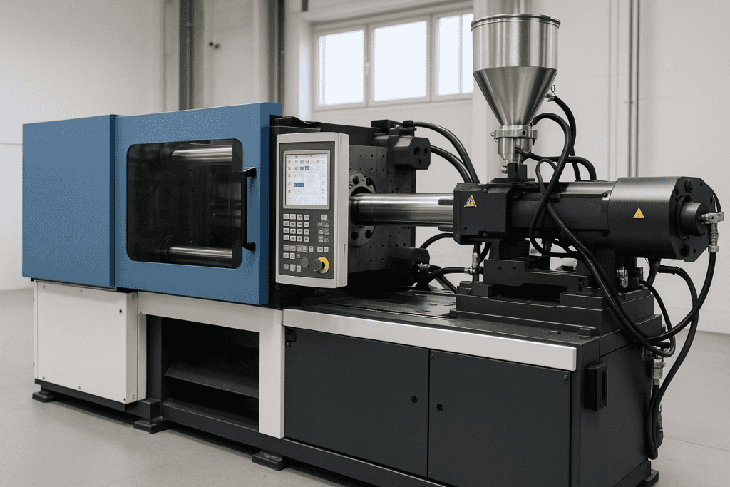
What Injection Moulding Equipment Includes
Injection moulding equipment covers the machines and support systems that melt polymer, inject the melt into a mould, then cool and eject the finished part. The core unit is the injection moulding machine, which combines an injection unit (hopper, heated barrel, screw and nozzle) with a clamping unit that holds the mould shut under pressure. Manufacturers specify clamp force, shot size and injection pressure to match the part volume and the mould design, while considering resin type, melt temperature and required tolerances.
The mould forms the component and includes cavities, runners or hot runners, gates, vents and ejection hardware. Temperature control equipment, such as water or oil circuits and a chiller or heater, keeps the mould within a stable range to protect quality and cycle time. Material handling equipment may include dryers, loaders and blenders, since moisture and inconsistent mix ratios can cause defects. Many lines also use robots or conveyors for part removal and packing, plus granulators for regrind. Process monitoring and safety systems, guided by standards from BSI, support repeatable production and safe operation, with alarms and interlocks that reduce downtime and operator risk.
 Injection Moulding Equipment
How Injection Moulding Machines Work: Core Stages
Injection moulding machines run a repeatable cycle that turns polymer pellets into consistent parts. Operators set temperature zones, screw speed, back pressure and clamp settings to suit the material and mould design. Once the machine reaches stable conditions, the cycle begins and repeats with tight control of time, pressure and position.
During plasticising, pellets feed from the hopper into a heated barrel. A rotating screw conveys, compresses and melts the polymer through a mix of heater input and shear heating from screw motion. The screw then retracts to build a measured shot in front of the screw tip. At this stage, the machine aims for a uniform melt temperature and a stable shot size, since variation here often shows as weight drift or surface defects.
Next, the clamping unit closes the mould and applies sufficient clamp force to resist cavity pressure. The injection phase pushes the screw forward like a plunger, forcing melt through the nozzle, sprue and runners into the cavity. As the cavity fills, the machine switches from velocity control to pressure control at a defined transfer point. Packing and holding pressure then compensate for material shrinkage as the polymer cools, helping to prevent sink marks and voids while maintaining dimensional accuracy.
Cooling starts as soon as the cavity fills. Water or oil circuits in the mould remove heat until the part reaches ejection stiffness. While cooling runs, the screw usually plasticises the next shot to reduce cycle time. Once cooling completes, the clamp opens and the ejection system pushes the part and runner out. The cycle then restarts, with process monitoring and troubleshooting support available from specialists such as Injection Moulders when production demands higher consistency or shorter cycles.
Machine Types and Configurations: Hydraulic, Electric, and Hybrid
Injection moulding machines typically fall into three categories: hydraulic, all-electric, and hybrid. Each configuration uses a different method to generate clamp force and drive screw movement. Selection should align with part tolerance, cycle time, material behaviour, and site constraints such as power supply and noise limits.
Hydraulic machines
Hydraulic machines use oil-driven pumps and valves to power the screw and clamping unit. Many moulders choose this type for high clamp forces, robust performance, and suitability for demanding applications such as thick-walled parts or large moulds. Hydraulic systems also tolerate shock loads well, which can help in processes that involve high injection pressures.
Energy use can rise when pumps run continuously, although modern servo-hydraulic designs reduce waste by matching pump output to demand. Maintenance focuses on fluid condition, seals, hoses, and filtration. Good housekeeping matters because oil leaks can affect safety and cleanliness. Noise levels may also exceed those of electric machines, so site layout and acoustic controls can influence the decision.
All-electric machines
All-electric machines drive the screw, injection, and clamp axes with servo motors and ball screws. This approach often delivers strong repeatability, fast response, and clean operation. Many manufacturers specify electric machines for tight-tolerance parts, thin-wall packaging, and medical or electronics components where cleanliness and consistent shot control matter.
Electric machines usually consume less energy than traditional hydraulics because motors draw power mainly when they move. The absence of hydraulic oil reduces contamination risk and can simplify compliance in controlled environments. On the other hand, electric machines can cost more upfront, and very high clamp force requirements may push a project towards hydraulic or hybrid options. For guidance on energy efficiency and process control principles, refer to resources from British Plastics Federation (BPF).
Hybrid machines
Hybrid machines combine elements of both systems, such as an electric screw drive with a hydraulic clamp, or servo-hydraulic pumps paired with electric axis control. This configuration aims to balance energy efficiency, force capability, and precision. Many moulders use hybrids for medium-to-large parts where clamp force remains high, yet process stability and reduced energy use still matter.
Hybrids can also offer flexible performance across a wider range of moulds. Even so, the mixed architecture can increase system complexity. Maintenance teams must understand both electrical servo systems and hydraulic circuits, and spares planning should reflect that.
Configuration choices that affect performance
- Clamp design: Toggle clamps often suit high-speed cycling, while hydraulic clamps can provide direct, adjustable force for large moulds.
- Drive and control: Closed-loop control (feedback from sensors) improves repeatability for pressure, position, and speed.
- Screw and barrel specification: Screw geometry and barrel metallurgy should match the polymer and any fillers to reduce wear and maintain melt quality.
- Machine footprint and utilities: Consider power availability, cooling water capacity, and any need for low-noise operation.
When comparing machine types, focus on measurable outcomes: part consistency, cycle time, scrap rate, and energy per part. A short, structured trial on representative tooling often provides clearer evidence than specification sheets alone.
Clamping Units: Tonnage, Platens, and Tie Bars
The clamping unit keeps the mould closed while the injection unit fills the cavity. Clamp force, measured in tonnes (tonnage), must exceed the force that melt pressure creates on the projected area of the part and runner system. If tonnage is too low, the mould can open slightly and cause flash. Excess tonnage can waste energy and increase wear on mould parting faces and tie bars. Many processors use a safety margin, then confirm settings during trials with cavity pressure data and part inspection.
Platens support and align the mould halves. Platen size sets the maximum mould footprint, while platen thickness and stiffness affect how evenly the clamp load spreads across the mould. Uneven support can lead to parting line mismatch, localised flash, and accelerated mould wear. Parallelism also matters, since poor platen alignment can distort the mould during clamping. When evaluating a machine, check daylight (maximum opening), stroke, and the distance between tie bars, since each limit can restrict mould choice even when tonnage appears sufficient.
Tie bars carry most of the clamp load and guide platen movement. Tie bar spacing must suit the mould base, yet clearance alone does not guarantee good performance. Tie bar stretch influences clamp force accuracy, so machines rely on calibration and feedback to maintain repeatable tonnage. Regular checks of tie bar lubrication, nut condition, and platen wear help prevent binding and uneven load. Guidance from machine builders such as ARBURG and ENGEL highlights the value of correct mould mounting and clamp set-up to protect tooling and maintain stable part quality.
 Injection Units: Screw Design, Barrel Heating, and Nozzles
Injection Units: Screw Design, Barrel Heating, and Nozzles
The injection unit prepares a stable melt and delivers it to the mould at the required pressure and speed. Three elements drive performance: screw design, barrel heating, and the nozzle interface. When these components match the polymer and part geometry, the process achieves consistent fill, low scrap, and predictable cycle times.
Screw geometry controls how pellets melt, mix, and build pressure. Most machines use a general-purpose, three-zone screw (feed, compression, metering). However, processors often specify alternative designs for demanding materials. A barrier screw improves melting efficiency by separating solid bed and melt, while a mixing section can improve colour dispersion and additive distribution. Screw diameter and L/D ratio (length-to-diameter) also matter: larger diameters raise shot capacity, whereas higher L/D ratios can improve melt homogeneity but may increase residence time for heat-sensitive polymers.
Barrel heaters and temperature zones maintain the melt profile along the screw. Band heaters supply heat, yet shear heating from screw rotation often contributes a large share of energy. Operators tune setpoints to avoid unmelted granules, burn marks, and excessive viscosity variation. Closed-loop control with thermocouples helps reduce drift, while good insulation limits heat loss and improves energy efficiency. For practical guidance on processing temperatures and material behaviour, consult polymer supplier data and references such as British Plastics Federation (BPF).
The nozzle forms the final seal between barrel and mould sprue bush. A poor match can cause drool, stringing, or leakage. Open nozzles suit many commodity polymers, whereas shut-off nozzles reduce drool for low-viscosity materials. Nozzle tip radius, orifice diameter, and heater capacity should align with sprue design and injection rate to prevent freeze-off while limiting shear and pressure loss.
- For stable filling: match screw design to polymer and required mixing.
- For repeatable melt quality: balance barrel setpoints with screw speed and back pressure.
- For clean transfer to the mould: select a nozzle type and tip geometry that seals reliably.
Mould Tooling and Ancillary Hardware: Hot Runners, Ejectors, and Cooling
Mould tooling converts machine pressure and heat into a controlled flow path, reliable release, and repeatable cooling. Hot runner systems keep polymer molten inside heated manifolds and nozzles, which reduces runner waste and can shorten cycle time. Gate type and thermal balance matter, since uneven heating can cause colour shift, stringing, or inconsistent fill. Suppliers such as Mold-Masters and Husky publish guidance on valve gates, thermal control, and maintenance intervals.
Ejection hardware then removes the part without damage. Standard ejector pins suit many rigid parts, while sleeves, stripper plates, and air assist help with deep cores or delicate features. Draft angle, surface finish, and ejector layout must work together, since poor support can leave witness marks or cause distortion. Cooling hardware often has the largest effect on cycle time and dimensional stability. Conventional drilled channels remain common, yet complex parts may benefit from conformal cooling, which follows the cavity shape more closely. Designers often validate cooling with simulation and follow recognised guidance such as PLASTICS resources to reduce warpage, sink, and residual stress.
Material Handling Equipment: Dryers, Loaders, and Conveying Systems
Why material handling matters
Material handling equipment sits between raw material storage and the machine hopper. That position makes it critical for part quality, uptime, and cost control. Stable feed rates reduce short shots and weight variation, while clean, dry pellets help prevent surface defects and weak mechanical properties. A well-designed handling set-up also limits manual lifting and reduces the chance of contamination from open bags, mixed regrind, or airborne dust.
Dryers: controlling moisture before processing
Many polymers absorb moisture from air. If that moisture enters the barrel, it can form steam and break polymer chains during melting. The result often includes splay marks, bubbles, odour, and reduced impact strength. Dryers remove moisture to a specified level before the material reaches the hopper. Desiccant dryers suit hygroscopic materials such as nylon (polyamide) and PET, while hot-air dryers can work for non-hygroscopic materials where surface moisture drives the risk.
Effective drying depends on temperature, airflow, and residence time. Dew point monitoring provides a practical check on desiccant performance, since a low dew point indicates dry process air. Processors often use hopper loaders with sealed connections to keep dried pellets isolated from humid shop air. For material guidance, the Plastics Industry Association provides resources on plastics processing and handling.
Loaders: consistent feeding with less handling
Loaders move pellets from a source container to the machine hopper or to a drying hopper. Vacuum loaders are common because they transfer material in closed lines, which helps keep pellets clean. Correct sizing matters: an undersized loader can starve the machine during high output, while an oversized unit can cycle too aggressively and increase filter maintenance. Sensors in the hopper or receiver manage demand, while filters protect the vacuum generator and reduce dust carryover.
Conveying systems: central supply and clean transfer
Conveying systems connect silos, gaylords, blenders, dryers, and multiple presses. Centralised vacuum conveying can support many machines from one material room, which improves housekeeping and simplifies inventory control. Dedicated lines reduce the risk of cross-contamination between colours or polymers, while purge stations and line cleaning routines support faster changeovers. Processors should also manage conveying velocity to limit pellet degradation and fines, especially with brittle materials.
When selecting equipment, compatibility with regrind, additives, and abrasive fillers matters. Suppliers such as Maguire and motan publish specifications that help match dryers, loaders, and conveying hardware to throughput, material type, and plant layout.
Process Control and Monitoring
Process Control and Monitoring: Sensors, Closed-Loop Control, and Data Logging
Process control and monitoring keep an injection moulding process stable from shot to shot. Modern machines measure key variables in real time, then use control logic to hold those variables within set limits. That approach reduces scrap, improves dimensional consistency, and supports repeatable start-ups after stoppages.
Sensors provide the raw signals. Barrel thermocouples track heater zone temperatures, while pressure transducers measure melt pressure in the nozzle, barrel, or cavity. Linear encoders monitor screw position and velocity, and clamp sensors confirm platen position and mould protection limits. Many tools also use cavity pressure sensors to show the true fill and pack behaviour inside the mould, which often reveals issues that machine-side readings cannot detect.
Closed-loop control uses sensor feedback to correct the process during the cycle. For example, the machine can regulate injection velocity based on screw position, then switch to holding pressure at a defined transfer point. When cavity pressure control is available, the system can end fill or adjust pack to hit a target pressure curve, which helps manage shrinkage and part weight variation. Temperature control loops also stabilise melt preparation by adjusting heater output and, where fitted, screw recovery settings.
Data logging turns monitoring into evidence. Machines record trends such as peak injection pressure, cushion, recovery time, cycle time, and alarm history. Engineers use those records to set process windows, compare shifts, and trace quality issues to specific events. For regulated production, electronic batch records and audit trails support compliance and reduce reliance on manual checks.
Many processors link machines to a plant network for central dashboards and alerts. Standards such as EUROMAP define common interfaces for data exchange, which simplifies integration with manufacturing execution systems and quality databases.
Maintenance, Safety, and Compliance: Guarding, Lockout, and Standards
Planned maintenance protects part quality, reduces downtime, and limits risk. A practical schedule covers lubrication points, tie bar inspection, clamp alignment checks, heater band condition, and screw and barrel wear measurement. Cleanliness also matters: purge safely, remove pellet dust, and keep guarding windows clear so operators can spot abnormal movement or leaks early.
Safety controls must prevent access to hazardous motion and hot surfaces. Fixed and interlocked guards should block the clamp area during automatic cycling, while light curtains and safety gates need routine function tests. Lockout and tagout procedures must isolate electrical, hydraulic, pneumatic, and thermal energy before any work begins. That includes releasing stored pressure, supporting moving platens, and verifying zero energy at the point of use.
Compliance relies on documented risk assessment, training, and inspection records. In the United Kingdom, processors often align machinery safety with HSE guidance on PUWER and follow relevant harmonised standards such as ISO 20430 for injection moulding machines. Clear signage, competent supervision, and controlled access to settings help maintain safe, repeatable operation during set-up, production, and maintenance.
Selection Criteria and Total Cost of Ownership for Injection Moulding Equipment
Selection starts with part requirements and production targets. Match clamp tonnage and shot size to the mould and polymer, then confirm that injection speed, pressure capacity, and recovery rate support the planned cycle time. Consider platen size, tie bar spacing, and mould height range to avoid costly compromises in tooling. Control capability also matters: specify repeatable closed-loop control for pressure, velocity, and temperature, plus data export that suits plant reporting and traceability needs.
Total cost of ownership extends well beyond purchase price. Energy use often dominates lifetime spend, so compare measured kWh per kilogram for the intended material and cycle, not brochure ratings. Maintenance costs depend on component access, parts availability, and service support, while downtime risk links to build quality and local engineering coverage. Evaluate consumables such as heater bands, check rings, and filters, then factor in training time for setters and operators. For safety and compliance, align specifications with recognised guidance from HSE and relevant standards such as BSI publications. A structured acceptance test, using representative moulds and materials, provides the clearest view of real operating cost.
FAQ
Q: How do I size an injection moulding machine for a new part?
Estimate shot weight from part volume, material density, and runner system. Choose shot capacity that runs in a stable window, not at the limits. Confirm clamp force from projected area and cavity pressure, then check platen size, tie bar spacing, and daylight for mould fit.
Q: What causes short shots and inconsistent part weight?
Typical causes include unstable melt temperature, restricted feed, air traps, and low injection speed or cavity pressure. Ensure dry, clean material, keep the feed throat clear, and hold a consistent transfer point from fill to pack. Where available, a cavity pressure trace can show whether filling or packing drives the variation.
Q: When should a business choose an all-electric machine?
All-electric machines suit high repeatability, clean operation, and lower energy use. They often suit thin-wall and tight-tolerance parts. Confirm injection rate and pressure match the polymer and gate design, since some jobs still suit hydraulic power density.
Q: How can I reduce cycle time without increasing scrap?
- Optimise cooling, since it often dominates the cycle.
- Cut pack and hold time after confirming gate freeze time.
- Stabilise melt preparation to avoid longer cycles masking defects.
- Use process monitoring to spot drift early and reduce rework.
Q: Which standards and guidance should I reference for safety?
Use recognised machinery safety guidance and ensure guarding and interlocks meet requirements. For UK and EU-aligned expectations, consult the Health and Safety Executive (HSE) guidance on work equipment and machinery. Follow supplier safety instructions as part of site procedures.
Q: What information should I request when comparing suppliers?
Request repeatability evidence, energy data, service response, spare parts availability, and controls such as data logging and alarm history. Ask for acceptance tests that match the part, mould, and material.