Wall thickness has a direct effect on the strength, weight, and cost of plastic parts. It also influences mould filling, cooling time, and the risk of defects such as warping, sink marks, and voids. Clear guidelines help designers choose dimensions that suit the polymer, the process, and the part function. This overview explains practical thickness ranges and key design checks to support consistent quality and efficient production.
Key takeaways
- Keep wall thickness uniform to reduce sink marks, warpage, and internal stress.
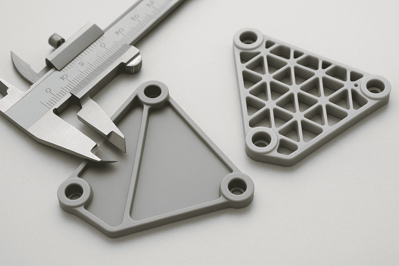
- Avoid thick sections; use ribs or coring to maintain strength without excess material.
- Use gradual transitions and radii between thickness changes to improve mould filling.
- Select thickness ranges based on resin type, as flow and shrinkage vary.
- Design ribs at a fraction of nominal wall thickness to prevent read-through.
- Account for cooling time, as thicker walls increase cycle time and cost.
Why wall thickness matters in plastic part design
Wall thickness shapes how a plastic part fills, cools, and performs. When designers choose a consistent thickness, molten polymer flows with less resistance and reaches fine features before it cools. As a result, the moulding cycle stays stable and scrap rates tend to fall. In contrast, thick-to-thin transitions often create hesitation in flow, which can leave short shots, visible flow lines, or weak knit lines where two flow fronts meet.
Cooling drives many quality outcomes. Thick sections hold heat longer than thin sections, so uneven thickness causes uneven shrinkage. That imbalance can pull a part out of shape and lead to warpage, sink marks, or internal stress. Designers can reduce these risks by keeping walls as uniform as the geometry allows and by using gradual transitions where changes are unavoidable. A stable wall also supports predictable dimensional control, which matters when parts must fit with tight tolerances.
Mechanical performance also depends on thickness, yet strength does not rise in a simple linear way. A thicker wall can improve stiffness, but it can also increase weight, material cost, and cycle time. Thin walls can reduce cost and improve cooling, although thin features may crack under load or during assembly. For that reason, designers should match thickness to the polymer type, expected loads, and joining method, such as snap-fits, screws, or ultrasonic welding.
Manufacturing constraints link directly to wall choices. Gate size, runner layout, venting, and mould temperature all interact with thickness, so early collaboration with Plastic Part Manufacturers helps to align design intent with process capability. For authoritative background on polymer behaviour and processing, guidance from British Plastics Federation can support material selection and realistic expectations for shrinkage and stability.
Recommended wall thickness ranges by polymer family and process
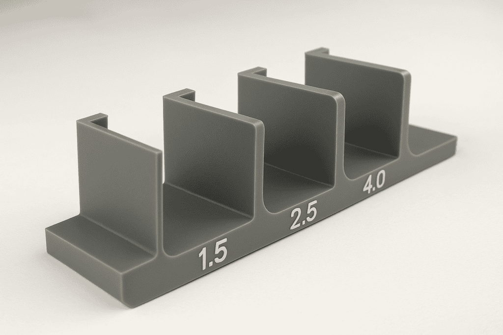
Wall thickness targets vary by polymer family because each material flows, shrinks, and cools in a distinct way. Process choice also matters. Injection moulding can produce thin, repeatable walls, while thermoforming and blow moulding usually need thicker sections to control sag and maintain stiffness. Use the ranges below as starting points, then confirm the final value with mouldflow simulation and supplier data for the exact grade. Keep wall thickness as uniform as possible, since abrupt changes often cause sink marks, warpage, and uneven packing. Where transitions are unavoidable, use gradual tapers and consistent rib proportions to support the section.
| Polymer family | Injection moulding (typical wall range) | Thermoforming (typical wall range) | Blow moulding (typical wall range) |
|---|---|---|---|
| Polypropylene (PP) | 0.8–3.0 mm | 1.0–4.0 mm | 1.5–5.0 mm |
| Polyethylene (HDPE/LDPE) | 1.0–4.0 mm | 1.0–5.0 mm | 1.5–6.0 mm |
| ABS | 1.0–3.5 mm | 2.0–6.0 mm | Not common |
| Polycarbonate (PC) | 1.0–4.0 mm | 2.0–6.0 mm | Not common |
| Polyamide (PA, nylon) | 0.8–3.0 mm | Not common | Not common |
| POM (acetal) | 0.8–3.0 mm | Not common | Not common |
| PMMA (acrylic) | 1.0–4.0 mm | 2.0–8.0 mm | Not common |
| PVC (rigid) | 1.0–4.0 mm | 1.5–6.0 mm | 2.0–8.0 mm |
These ranges assume unfilled grades. Glass or mineral fillers often raise viscosity and can push minimum practical thickness upwards, while elastomers may need extra section to meet stiffness targets. When a design needs thin walls for weight or space, prioritise polymers with good flow and specify generous radii to reduce stress. For thick walls, expect longer cooling times and plan for coring or ribbing to achieve stiffness without excessive section. Also check tolerance and flatness requirements, since tighter specifications can demand thicker walls or local reinforcement to control distortion.
For production-ready guidance, confirm the target thickness with your moulder and the resin supplier. A specialist such as Injection Moulders can advise on achievable limits for the selected tool, gate strategy, and cosmetic requirements. Ask for feedback on draft angles and ejection, as both can influence the minimum wall that remains robust during demoulding.
Design rules for uniform walls, transitions, ribs and bosses
Uniform wall thickness remains the most reliable way to control filling, packing and cooling. Aim to keep nominal walls consistent across the part, then achieve stiffness through geometry rather than local thickening. When a design needs a change in section, use a gradual transition so the melt front stays stable and the cooling rate remains even. As a practical rule, use a taper or radius rather than a sharp step, and avoid sudden jumps that concentrate shrinkage and create sink marks.
Transitions require attention at corners and junctions. Use generous internal radii to reduce stress concentration and support flow, while keeping external radii consistent with the internal radius plus the nominal wall. Where a thick feature must meet a thin wall, core out the thick region to maintain a near-uniform section. This approach also reduces the risk of voids in semi-crystalline polymers, which can shrink more during cooling.
Ribs add stiffness with limited mass, but rib geometry must respect the base wall to prevent sink and read-through. Set rib thickness below the nominal wall and use draft so the tool releases cleanly. Maintain a fillet at the rib root to reduce notch sensitivity, and space ribs to avoid creating a locally thick “grid” that cools slowly. When ribs intersect, consider staggering or reducing height at the crossing to limit heat build-up.
Bosses often drive cosmetic defects because they create thick sections around fasteners. Use cored bosses and connect them to nearby walls with ribs rather than solid pads. Keep the boss base blended with radii, and provide draft on both the inner and outer walls. For threaded inserts, follow the insert supplier’s recommendations and validate with mouldflow analysis; Autodesk Moldflow provides a widely used reference workflow for predicting sink, warpage and weld lines.
Common wall thickness defects, root causes and practical fixes
Wall thickness defects often appear as cosmetic marks, dimensional drift, or reduced strength. Most issues trace back to uneven cooling, poor packing pressure, or abrupt section changes. A structured check of the defect pattern and the local geometry usually identifies the cause quickly.
Sink marks and surface read-through commonly form above ribs, bosses, and other local mass. Excess material cools slowly, then shrinks after the skin has set. Reduce the local wall by coring out thick areas, keep rib thickness proportionate to the nominal wall, and add generous radii at intersections to support flow without creating a heat sink. When tooling changes are not possible, adjust packing pressure and time to compensate, while monitoring for flash.
Warpage and twist tend to result from non-uniform shrinkage across the part. Uneven wall thickness, unbalanced gating, or inconsistent cooling circuits can pull the part out of shape as it ejects. Improve symmetry where feasible, balance the fill pattern with gate location changes, and confirm cooling uniformity. Use mouldflow analysis to validate the plan; Autodesk Moldflow provides a standard reference for predicting shrinkage-driven distortion.
Short shots, flow lines, and weak knit lines often indicate hesitation at thick-to-thin transitions or long flow lengths for the selected wall. Increase local thickness only if the design allows, but prioritise smoother transitions, larger radii, and improved venting to prevent trapped air. If knit lines fall in a high-stress zone, reposition gates or add flow leaders so the melt fronts meet hotter and under higher pressure.
Flash at parting lines and around inserts can rise when designers increase packing to overcome sinks in thick regions. Address the root cause by removing excess mass and stabilising wall thickness, then re-optimise clamp force and packing settings to restore a robust process window.
Frequently Asked Questions
What wall thickness range suits most injection-moulded plastic parts?
Most injection-moulded plastic parts suit a wall thickness of about 1.0 to 3.0 mm. Many designs perform well near 2.0 mm, depending on resin type, part size, and strength needs. Keep walls as uniform as possible to reduce sink marks, warpage, and uneven cooling.
How does wall thickness affect sink marks, warpage, and cycle time in plastic moulding?
Wall thickness controls how plastic cools and shrinks. Thick sections cool slowly, which raises sink marks and extends cycle time. Uneven thickness causes uneven shrinkage, which increases warpage. Thin walls cool faster and reduce sinks, yet overly thin walls can create short shots and stress. Aim for uniform thickness with gradual transitions.
When should a plastic part use variable wall thickness instead of a uniform wall?
Use variable wall thickness when the part needs local strength, stiffness, heat control, or space for features such as bosses, ribs, inserts, or threads. Apply it to manage flow length, reduce sink marks, and limit warpage in large or complex mouldings. Keep transitions gradual and avoid abrupt steps to prevent stress and poor filling.
How do ribs and gussets improve stiffness without increasing wall thickness?
Ribs and gussets raise stiffness by adding depth and support where bending occurs, which increases the section’s moment of inertia without thickening the main wall. Ribs act as thin webs that resist flex, while gussets brace corners and joints to spread loads. Use gradual transitions and adequate draft to limit sink and stress.
What wall thickness guidelines apply when designing plastic parts for 3D printing versus injection moulding?
For 3D printing, use thicker walls to suit the process: about 0.8–1.2 mm for FDM and 1.0–2.0 mm for SLA, with at least 2–3 perimeters. For injection moulding, aim for uniform walls, typically 1.0–3.0 mm, with smooth transitions, ribs for stiffness, and draft angles to aid ejection.