Draft angles shape how easily a moulded part releases from its tool. A small taper on vertical walls reduces friction, limits scuffing, and helps protect both the component and the mould. Good draft also supports consistent dimensions, cleaner surface finish, and shorter cycle times. Without enough draft, parts can stick, warp, or require extra force to eject, which raises scrap rates and maintenance needs. This guide explains what draft angles are and why designers specify them.
Key takeaways
- Draft angles let parts release cleanly from moulds without scuffing or sticking.
- Insufficient draft increases ejection force, raising the risk of part distortion and damage.
- Surface texture and finish often require extra draft to prevent drag marks.
- Deep ribs, bosses, and pockets need careful draft to avoid seizure on core features.
- Material shrinkage and moulding method influence the draft angle required for reliable release.
- Early draft planning reduces tooling rework and improves cycle time and scrap rates.
What draft angles are and how they work in moulded parts
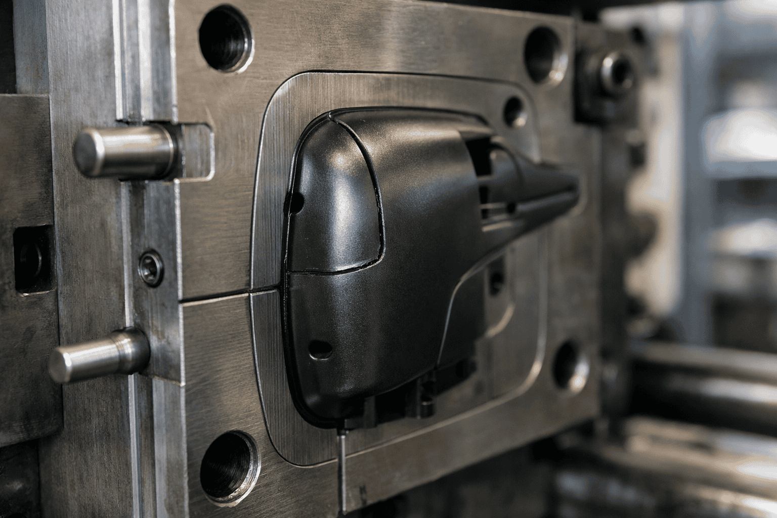
A draft angle is a slight taper built into the vertical faces of a moulded feature. Instead of forming a perfectly straight wall, the mould creates a controlled slope that helps the part release from the tool. Without that taper, the plastic can grip the mould surface as it cools and shrinks, which raises the risk of scuffing, drag marks, or distortion during ejection.
Draft works because injection moulding relies on two tool halves separating cleanly along a parting line. As the mould opens, the core side usually holds the part, while ejector pins push the part off the core. A suitable draft angle reduces contact pressure and friction between the plastic and the steel, so ejection needs less force. Lower ejection force protects fine details, reduces stress whitening, and supports consistent cycle times.
Several factors influence how much draft a feature needs. Surface texture often drives the requirement, since a textured finish increases mechanical grip and needs extra taper to release cleanly. Material choice also matters, because different polymers shrink at different rates and can cling to the tool in different ways. Feature height plays a part as well; taller walls create more contact area, so they usually need more draft than shallow ribs or bosses.
Draft angles affect both appearance and function. Designers must balance release needs with dimensional targets, especially on snap fits, sealing faces, and cosmetic surfaces. Early alignment between design and tooling teams prevents late changes and avoids compromising performance. For context on how these design choices translate into production outcomes, see Plastic Moulded Parts.

How draft angles affect ejection, surface finish, and tool wear
Draft angles influence three practical outcomes in injection moulding: how easily the part ejects, how clean the surface looks, and how quickly the tool components wear. Each effect links to friction between the moulded plastic and the cavity or core during release.
During ejection, insufficient draft increases contact area and raises sliding resistance. As a result, ejector pins must apply higher force to move the part, which can leave pin witness marks, stress whitening, or local deformation on thin walls. Parts may also stick on one side, causing cocking during ejection and creating edge damage on ribs, bosses, or shut-offs. A suitable draft angle reduces the force needed, stabilises release, and supports consistent cycle times.
Surface finish also depends on draft because texture and gloss change how strongly the plastic grips the steel. A polished cavity can still scuff if the wall runs near-parallel to the draw direction, since the part drags along the surface as it moves. Textured finishes amplify this effect because the texture creates mechanical interlock. For that reason, textured faces usually need more draft than smooth faces to prevent drag lines and to keep the texture uniform after repeated cycles. Guidance from PLASTICS supports the principle that texture depth and resin shrinkage both influence draft requirements.
Tool wear rises when draft is too small because higher ejection loads increase abrasion and galling on cores, cavity walls, and sliding shut-offs. Wear then changes the effective geometry, which can lead to flash, loss of detail, and more frequent polishing or rework. Adequate draft reduces rubbing, protects coatings, and helps maintain dimensional stability across long production runs.
Draft angle guidelines by material, texture, and part geometry
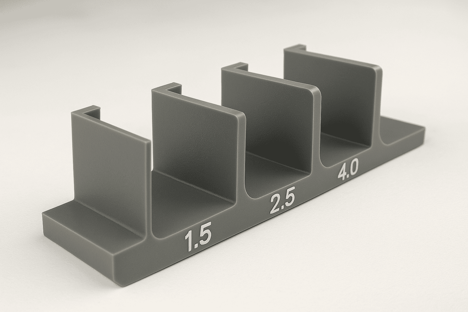
Draft requirements change with resin choice, surface texture, and the shape of the feature. A practical baseline for many injection-moulded plastics sits around 1° per side on external walls and 2° per side on internal walls, since cores tend to hold parts more tightly. Semi-crystalline materials such as polypropylene and polyethylene often shrink more and can release well with modest draft, provided the surface stays smooth. Amorphous materials such as polycarbonate and ABS can show higher friction against steel, so extra draft can reduce scuffing and stress whitening on ejection.
Surface texture usually drives the largest increase. As texture depth rises, the moulded surface forms mechanical “keys” against the tool, so the part needs greater taper to clear the peaks without dragging. For light textures, a small increase above the baseline often suffices. Medium to heavy textures typically need several degrees per side, and deep grained finishes may require substantially more. When a specific texture standard applies, confirm draft against the texture supplier’s guidance, such as SPE finish references used across automotive interiors.
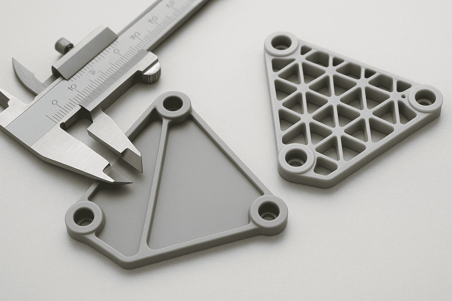
Part geometry can override material and texture rules. Tall ribs, deep bosses, and long shut-offs increase contact length, which raises sliding resistance even with smooth steel. Thin walls cool quickly and can grip the core, so designers often add draft early rather than relying on higher ejector force. Sharp corners also concentrate stress during release; a small radius at the base of ribs and bosses can reduce sticking and allow a lower draft than a square transition. Where function limits taper, consider local reliefs, polished tool surfaces, or re-orienting the parting line so critical faces draft in the direction of ejection.
How to specify draft angles on drawings and validate them in CAD
Specify draft clearly on the drawing so tooling and inspection teams apply the same intent. Place the draft call-out on the relevant face in the view that shows the pull direction, then state the angle per side and the datum that defines the direction of draw. A typical note format reads: “Draft 1.0° per side relative to datum A (tool opening direction)”. Where the parting line controls the start of the taper, dimension the feature at the parting line and identify the measurement plane. That approach avoids ambiguity because a drafted wall changes size along its height.
Include any surface texture requirement next to the drafted faces, since texture often drives the minimum draft. When the drawing uses geometric dimensioning and tolerancing, keep the draft note consistent with the datum scheme used to locate the feature. If a face must remain functionally straight in one axis, state that constraint explicitly and agree the compromise with the toolmaker, as draft and “straightness” can conflict.
Validate draft in CAD before release, using the same pull direction defined on the drawing. Most systems provide a draft analysis that colours faces by angle relative to the draw vector. Run the check on the final solid, not on early surfaces, and confirm that ribs, bosses, shut-offs, and textured areas meet the intended minimum. Pay close attention to local failures near blends and fillets, where a nominal angle can drop below target. Where the CAD tool reports “negative draft”, correct the geometry or adjust the parting strategy rather than relying on tool steel adjustments.
For traceability, capture screenshots of the draft analysis and record the pull direction and threshold angles used. When teams exchange CAD, share the native model and a neutral format such as STEP, aligned to the guidance from ISO 16792 for digital product definition, so the draft intent remains consistent across systems.
Frequently Asked Questions
What is a draft angle in mould design?
A draft angle is a slight taper on moulded part walls that allows the part to release from the mould without damage. Designers apply draft to faces parallel to the mould opening direction. Adequate draft reduces friction, prevents scuff marks, and supports consistent ejection, which improves part quality and shortens cycle times.
Why do draft angles reduce part sticking and ejection force?
Draft angles create a slight taper on moulded walls, which reduces contact area and friction as the part cools and shrinks onto the core. The taper also breaks vacuum and lowers adhesion, so the part releases sooner. As a result, ejector pins need less force, which cuts scuffing, stress marks, and distortion.
How does material shrinkage affect the draft angle you should specify?
Material shrinkage can tighten the part on the mould core as it cools, which increases ejection friction and scuff risk. Higher-shrink materials often need a larger draft angle, especially on deep walls, textured faces, and ribs. Lower-shrink materials may release with less draft, but always confirm with trials and toolmaker guidance.
What draft angle range suits textured or grained mould surfaces?
Textured or grained mould surfaces usually need larger draft angles than smooth faces. A practical range is 3° to 7° per side, with deeper or sharper textures often needing 5° to 10°. Use the texture depth, resin type, and part height to confirm the minimum draft that releases cleanly without scuffing.
How do you choose draft angles for deep ribs, bosses, and pockets?
Use larger draft angles as depth increases. For deep ribs, aim for at least 1° per side, then add about 0.5° for each extra 25 mm of depth. For bosses and pockets, use 1° to 2° per side, and increase if surfaces are textured. Keep wall thickness consistent to limit sink and distortion.
What problems can insufficient draft angles cause in moulded parts and tooling?
Insufficient draft angles can cause parts to stick in the mould, leading to high ejection force, scuffing, stress marks, and distortion. Tooling may suffer from accelerated wear, damaged ejector pins, and galling on cavity walls. Cycle times often increase due to slow release, while scrap rates rise from cosmetic and dimensional defects.
How do draft angles influence dimensional accuracy and cosmetic finish?
Draft angles reduce friction during ejection, which limits scuffing, drag marks, and stress whitening, improving cosmetic finish. Adequate draft also lowers the risk of part distortion and edge damage, helping dimensions stay closer to specification. Too little draft can cause sticking and wear; too much draft can shift critical widths and hole sizes.
When can you use zero draft, and what risks does it introduce?
Zero draft suits short runs, flexible materials, or parts with polished cores, strong ejection, and generous release agents. It also appears on non-cosmetic internal faces where slight scuffing is acceptable. Risks include sticking, drag marks, stress whitening, higher ejection force, tool wear, part distortion, longer cycle times, and increased scrap.