Introduction
Plastic injection moulding is a high-volume manufacturing process that forms plastic parts by injecting molten polymer into a precision tool (mould). UK manufacturers use it to produce consistent components with tight tolerances, repeatable quality, and efficient unit costs at scale. The method suits many sectors, from medical devices to automotive and consumer goods, because it supports complex geometries and a wide choice of materials. This guide explains how the process works, what affects quality and cost, and when injection moulding fits a production plan. For standards context

What plastic injection moulding is and why UK manufacturers use it
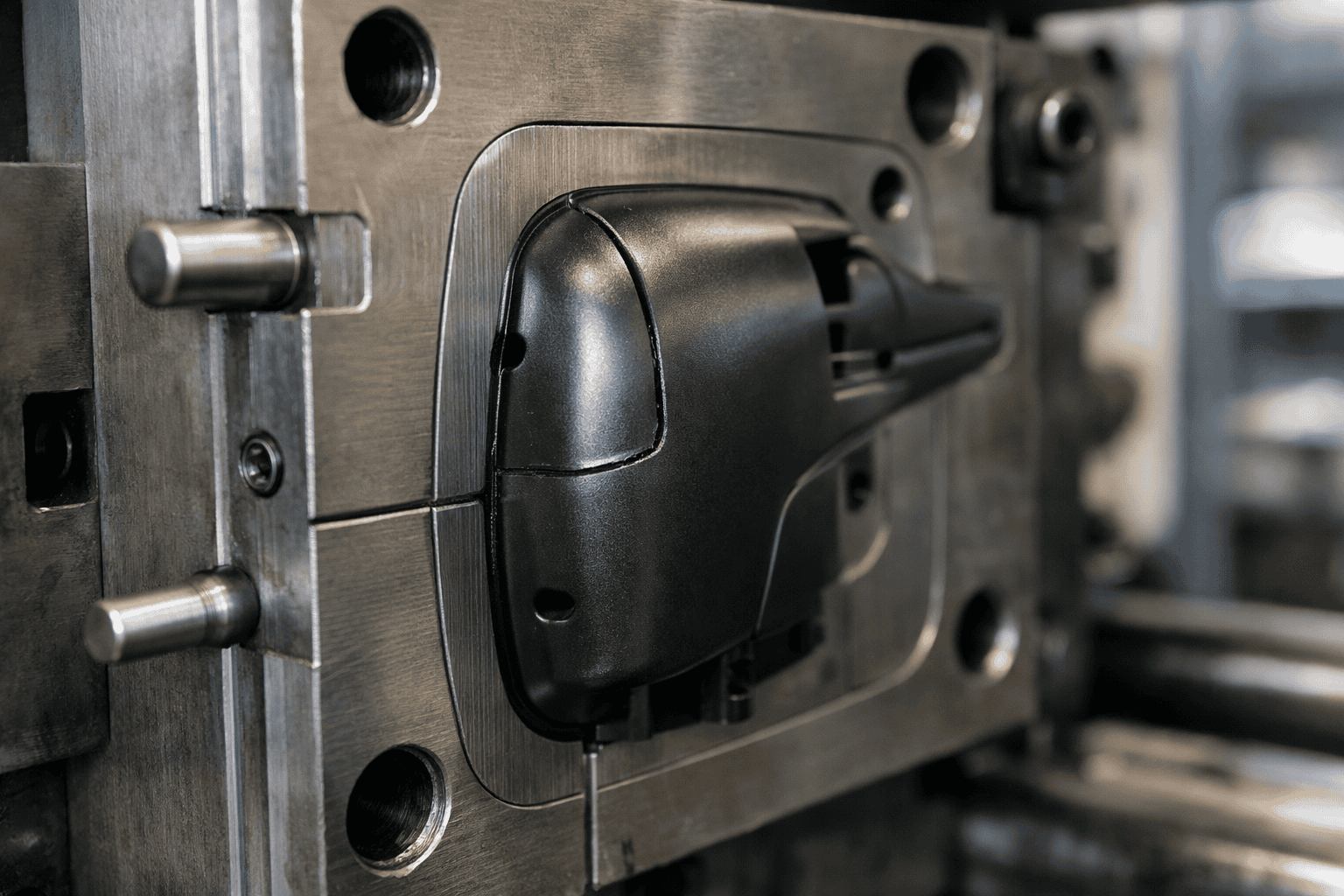
Plastic injection moulding is a production method that uses a heated barrel and a screw to melt plastic pellets, then forces the melt into a closed mould under pressure. The material cools and solidifies against the mould surfaces, after which the tool opens and ejector pins release the finished part. Manufacturers often automate each stage, which supports stable cycle times and consistent output. Process controls such as temperature, pressure, and cooling time help maintain repeatability across batches.
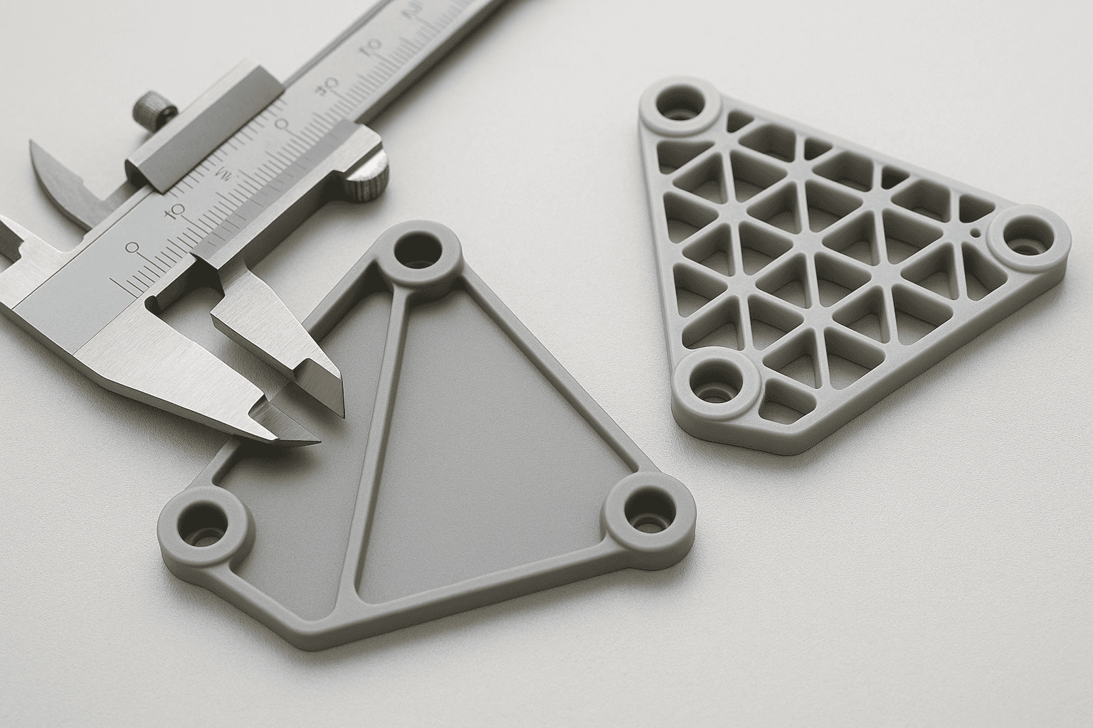
UK manufacturers use injection moulding because it suits repeatable production where dimensional accuracy and surface finish matter. The process also supports features such as ribs, bosses, clips, and snap-fits, which can reduce assembly steps and lower total cost. Tooling requires upfront investment, yet unit costs fall sharply as volumes rise, making the method attractive for long runs and established products. Tight tolerances also support interchangeability for service parts.
Material choice also drives adoption. Common polymers include polypropylene, ABS, nylon, and polycarbonate, each offering a different balance of strength, impact resistance, chemical resistance, and heat performance. Additives and colourants can also tailor stiffness, UV stability, and appearance to suit end-use needs. For a broader view of related processes and capabilities, see Plastic Manufacturing.
How the plastic injection moulding process works: step-by-step
1) Material preparation and drying
Most moulding grades arrive as pellets (granules). Before processing, a moulder checks polymer type, batch details, and any additives such as colour masterbatch. Many engineering plastics absorb moisture from the air, which can cause splay marks, bubbles, weak parts, and unstable dimensions.
Operators often dry hygroscopic materials (such as nylon and PET) in a dehumidifying dryer to the supplier’s specification. A moisture check confirms the pellets meet the target level before feeding into the hopper.
2) Plasticising: melting and mixing in the barrel
The machine feeds pellets from the hopper into a heated barrel. A rotating screw conveys, melts, and mixes the polymer using shear and heater bands, supporting stable colour and predictable flow.
The machine builds a measured “shot” in front of the screw. The controller sets barrel temperatures, screw speed, and back pressure. Back pressure can improve melt uniformity, but excessive settings may raise shear and degrade sensitive polymers.
3) Mould closing and clamping
Before injection, the mould closes and the clamp applies force to keep the tool shut. Correct clamp force prevents flash at the parting line, while avoiding excess wear and energy use.
Water or oil circuits regulate mould temperature to balance finish, cycle time, and dimensional stability.
4) Injection (fill): packing the cavity at speed
The screw drives forward and injects melt through the nozzle, sprue, runners, and gate into the cavity. The controller manages speed and pressure to fill before the gate freezes.
Many moulders use a velocity-to-pressure transfer point (V/P switchover): speed control during fill, then pressure control as the cavity nears full.
5) Hold (pack) pressure: controlling shrinkage
After fill, the machine applies hold pressure for a set time to compensate for shrinkage during cooling. Correct packing reduces sink marks, voids, and short shots, while improving weight and dimensional repeatability.
Once the gate solidifies, extra hold time adds cycle time without improving quality.
6) Cooling: solidifying the part
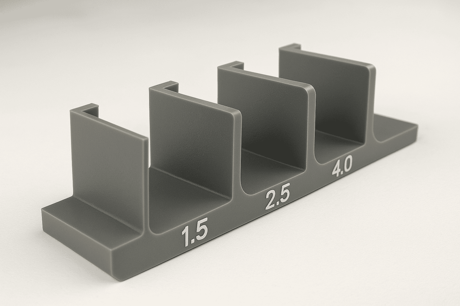
Cooling often takes the largest share of the cycle. Time depends on wall thickness, polymer type, mould temperature, and cooling channel efficiency.
Even cooling helps parts release cleanly and reduces warpage. Uneven cooling can distort parts as areas shrink at different rates.
7) Mould opening and ejection
When the part stiffens, the clamp opens the tool and ejector pins, sleeves, air blasts, or stripper plates release the part. Method choice depends on geometry, finish needs, and mark risk.
Robots or conveyors often remove parts to protect cosmetic surfaces and stabilise cycle time. Operators may separate runners and sprues when the tool does not use a hot runner system.
8) Finishing, inspection, and process control
Parts may need trimming, de-gating, or simple assembly. Checks cover dimensions, weight, appearance, and functional features. Many UK manufacturers use statistical process control (SPC) to monitor variation. The British Standards Institution (BSI) provides guidance on quality management standards used by many moulders.
Monitoring often tracks melt temperature, injection pressure, cycle time, and cushion (melt left in front of the screw after injection). Stable readings support repeatable output, while trends can indicate wear, blocked vents, or material changes.
A typical injection moulding cycle repeats these steps in seconds. Consistency comes from controlling material condition, melt preparation, tool temperature, and the fill-to-pack transition.
Core components of an injection moulding machine and their roles
An injection moulding machine combines several systems that work together to deliver repeatable parts. The injection unit includes a heated barrel, a reciprocating screw, and a non-return valve. Barrel heaters and shear from screw rotation melt and mix the polymer, while the screw then drives forward to inject a measured shot into the tool. A stable melt temperature and consistent shot size help maintain dimensions and surface finish.
The clamping unit holds the mould closed against injection pressure. Tie bars, platens, and a clamping mechanism generate and maintain clamp force, which prevents flash and protects the tool faces. The mould itself provides the cavity and core that form the part, plus runners, gates, and vents that guide flow and release trapped air. Cooling channels remove heat so the polymer solidifies at a controlled rate.
Ejection hardware, often pins or sleeves, pushes the part from the mould after opening. A hydraulic or electric drive powers clamp and injection movements, while sensors and a controller regulate temperature, pressure, speed, and time. Many UK sites align machine safety and guarding with guidance from the Health and Safety Executive (HSE).

Tooling and mould design essentials: cavities, runners, gates, and cooling
Tooling choices shape part quality, cycle time, and cost. A mould usually contains two halves that form the part geometry when clamped together. Designers specify the number of cavities, which means how many parts the tool produces per cycle. Single-cavity tools suit low volumes or large components, while multi-cavity tools reduce unit cost when demand supports the higher tooling spend. Family tools, which mould several different parts in one shot, can work well for matched sets, although balancing fill and cooling becomes more complex.
The runner system carries molten polymer from the machine nozzle to each cavity. Cold runners solidify with the part and create sprue and runner waste, while hot runner systems keep material molten and can cut scrap and improve consistency. Gate design then controls how the melt enters the cavity. A well-chosen gate position reduces weld lines, limits trapped air, and supports even packing. Common gate types include edge, pin, and submarine gates, each with different effects on appearance, vestige, and automation.
Cooling often sets the cycle time, so mould designers place cooling channels close to thick sections and around areas that drive shrinkage. Uniform cooling helps prevent warpage and sink marks, while poor cooling can cause dimensional drift and surface defects. Conformal cooling, made using additive manufacturing, can follow complex shapes and improve heat transfer, although it increases tool cost and lead time.
Tooling also needs practical features such as draft angles for release, venting to let air escape, and robust ejection to avoid marks or distortion. Material choice for the tool, surface finish, and wear protection matter when moulding abrasive or glass-filled polymers. For a deeper view of tool build options and design considerations, see Injection Moulding Tooling.
Materials for injection moulding: common polymers, additives, and selection criteria
Material choice drives part performance, appearance, compliance, and unit cost. Most moulders process thermoplastics, which soften when heated and solidify on cooling. Thermosets behave differently and suit specialist applications, so most UK production focuses on thermoplastics.
Common polymers include polypropylene (PP) for hinges and general-purpose parts, acrylonitrile butadiene styrene (ABS) for tough housings, and polyethylene (PE) for chemical resistance. Polycarbonate (PC) offers high impact strength and clarity, while polyamide (nylon, PA) provides strength and wear resistance but often needs drying. Polyoxymethylene (POM, acetal) suits low-friction gears and moving components. Polyethylene terephthalate (PET) and PBT support stable dimensions and good electrical properties. For demanding environments, engineering grades such as PEEK and PPS handle heat and chemicals, though material cost rises.
- Commodity polymers: PP, PE, PS, ABS for cost-sensitive, high-volume parts.
- Engineering polymers: PA, PC, POM, PET/PBT for strength, stability, and wear.
- High-performance polymers: PEEK, PPS for high temperature and aggressive media.
Additives tune behaviour and processing. Glass fibre increases stiffness but can raise tool wear and reduce surface finish. Impact modifiers improve toughness, while flame retardants support fire performance targets. UV stabilisers slow outdoor degradation, and lubricants can reduce friction and aid mould release. Colour usually comes from masterbatch, which concentrates pigment in a carrier resin.
Selection works best when it starts with requirements rather than a preferred resin. Key criteria include service temperature, chemical exposure, load and fatigue, dimensional tolerance, surface finish, and regulatory needs. For medical or food-contact parts, confirm grade approvals and traceability against relevant guidance from the Food Standards Agency or the MHRA. Material data sheets from suppliers such as Covestro and BASF help validate mechanical and thermal properties before tooling decisions lock in.
Quality control in injection moulding: tolerances, defects, and inspection methods
Quality control in injection moulding focuses on dimensional tolerances, cosmetic standards, and material performance. Tolerances describe the allowed variation from a nominal dimension, often set by part function, assembly fit, and polymer shrinkage. A capable process holds dimensions through stable melt temperature, consistent shot size, controlled packing pressure, and repeatable cooling. Many UK manufacturers use statistical process control (SPC) to track key dimensions and detect drift before parts fall out of specification.
Common defects include sink marks from uneven wall thickness, warpage from unbalanced cooling or orientation, flash from poor clamp force or worn tooling, short shots from insufficient fill, and splay from moisture or trapped gas. Each defect points to a specific cause, so teams link inspection findings to machine settings, tool condition, and material handling.
Inspection methods range from in-process checks to full dimensional verification. Operators often use calibrated callipers, micrometers, and go/no-go gauges for fast checks, while coordinate measuring machines (CMMs) confirm complex geometry. Visual inspection under controlled lighting supports consistent cosmetic grading. When compliance matters, traceable calibration and measurement practices aligned with ISO 9001 help demonstrate control and repeatability.

Cost and lead time drivers in UK injection moulding projects
Project cost and lead time in UK injection moulding depend on a small set of practical drivers. Tooling usually sits at the top of the cost stack because the mould must match the part specification and the target production rate. Complex geometry, tight tolerances, textured surfaces, and multiple cavities all increase machining time and toolmaking risk. Steel grade also matters: hardened tool steels cost more, yet they suit higher volumes and abrasive, glass-filled polymers.
Part design choices influence both price and schedule. Thin walls, deep ribs, undercuts, and demanding cosmetic faces often require side actions, lifters, or unscrewing mechanisms. Each moving feature adds build time, validation effort, and maintenance needs. Gate location and ejection strategy can also drive iterations if the part shows witness marks, warpage, or scuffing.
Cycle time sets the unit cost once production starts. Cooling usually controls cycle time, so efficient cooling channels and stable mould temperature reduce cost per part. Material selection affects cycle time as well, since some polymers need higher melt temperatures or longer cooling to meet dimensional and cosmetic requirements. Regrind use, colour changes, and purge time can raise scrap and reduce effective output, which increases unit cost.
Lead time also reflects the approval route. Sampling, dimensional inspection, and capability studies can extend schedules, especially for regulated products. When a programme needs early design confidence, Rapid Prototypes can reduce uncertainty before committing to full production tooling, which often shortens the number of tool revisions.
UK logistics and commercial terms play a role. Insert supply, packaging requirements, and delivery cadence affect planning, while tool ownership, spares, and maintenance agreements influence lifetime cost. Clear specifications and prompt feedback during sampling keep projects moving and help avoid avoidable rework.
UK compliance and sustainability considerations: regulations, recyclability, and waste reduction
UK injection moulding projects often sit within regulated supply chains, so compliance needs clear ownership from specification to production. Product safety and chemical restrictions may apply under UK REACH, while electrical and electronic products can trigger obligations under the WEEE Regulations and the RoHS Regulations. Packaging choices also matter, since the UK packaging waste regulations set recovery and recycling duties for obligated businesses.
Sustainability starts with material selection and part design. Designers can improve recyclability by avoiding mixed polymers, limiting fillers that hinder reprocessing, and choosing compatible colourants. Marking parts with polymer identification codes supports sorting and recycling. Process control also reduces waste: stable settings cut scrap, while hot runners can reduce runner waste where justified. Many moulders regrind sprues and runners for non-cosmetic parts, yet teams should confirm that regrind content does not compromise strength, appearance, or regulatory status.
Documentation underpins both compliance and environmental claims. Material data sheets, declarations of conformity, and traceability records help demonstrate control, while measured scrap rates and rework levels provide a practical baseline for waste reduction targets.
FAQ
What types of parts suit plastic injection moulding?
Injection moulding suits repeatable plastic components with consistent geometry, such as housings, clips, caps, brackets, and consumer product parts. It works best when the design supports stable filling and ejection, and when volumes justify a dedicated mould tool.
What is the difference between injection moulding and 3D printing?
Injection moulding uses a metal mould to produce parts at high speed with low unit cost at scale. 3D printing builds parts layer by layer without tooling, which suits prototypes and low volumes. Many UK manufacturers use 3D printing for early validation, then move to injection moulding for production.
How long does it take to start production?
Lead time depends on tool complexity, material availability, and validation requirements. Expect longer timelines for multi-cavity tools, tight tolerances, or regulated products. A clear specification and prompt feedback during tool trials help reduce delays.
Can injection moulded parts be recycled?
Many thermoplastics can be recycled, although outcomes depend on polymer type, additives, colour, and contamination. Regrind (reprocessed sprues and runners) can often return to the process in controlled proportions, subject to performance and customer requirements.
Which UK regulations commonly affect moulded plastic parts?
Requirements vary by product and market. Chemical restrictions may apply under UK REACH. Electrical products may need compliance with RoHS and the WEEE Regulations. Packaging obligations can arise under the UK packaging waste regulations.
What information should a manufacturer provide for an accurate quote?
- 3D CAD and 2D drawings with critical dimensions and tolerances
- Material specification (or performance targets if material is undecided)
- Expected annual volumes and forecast ramp-up
- Cosmetic requirements, colour, and surface finish
- Any compliance needs, test standards, and traceability expectations
Practical tip: If a dimension affects fit, sealing, or safety, identify it as critical and state how it will be measured. Clear inspection criteria reduce disputes and speed up approval.
Conclusion
Plastic injection moulding gives UK manufacturers a reliable route to consistent, high-volume parts when design, tooling, material choice, and process control align. The strongest outcomes come from clear specifications, early design-for-manufacture review, and measurable quality criteria that match the end use. Compliance and sustainability also benefit from planning, since polymer selection, regrind strategy, and documentation affect both cost and risk. When you need practical guidance on feasibility, tooling approach, and production readiness, speak with an experienced Injection moulding Company to confirm assumptions before committing to a mould build.